
Injection pump - without intercooler (page 4 of 4)
- Make
- Rover
- Model
- 400 Workshop Manual
- Year
- 1995–2000
- Section
- Repairs
Engine management system - EDCInjection pump - without intercooler · page 4 of 4
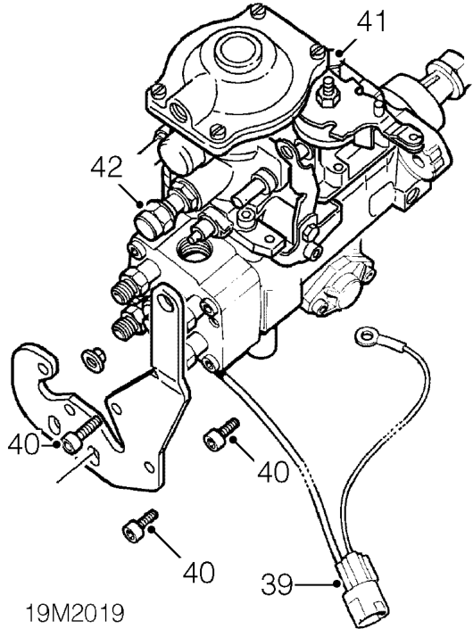
- Release FIP multiplug from abutment bracket.
- Remove 3 Allen screws securing abutment bracket to FIP and remove bracket.
- Remove fuel feed banjo adaptor from FIP and discard sealing washer.
- Remove fuel return banjo adaptor from FIP and discard sealing washer.
CAUTION: Plug the connections.
- Fit fuel return banjo adaptor to FIP using new sealing washer. tighten adaptor to 25 Nm.
- Fit fuel feed banjo adaptor to FIP using new sealing washer. Tighten adaptor to 25 Nm.
- Fit abutment bracket to FIP and tighten Allen screws to 10 Nm.
- Connect FIP multiplug to abutment bracket.
- Lubricate and fit new ’O’ ring to fuel cut-off solenoid.
- Clean fuel cut-off solenoid plunger and spring.
- Fit plunger and spring to solenoid.
- Fit solenoid to FIP and tighten to 20 Nm.
- Connect cable to solenoid and secure terminal nut.
Refit
- Clean mating faces of FIP and gearbox mounting plate.
- Fit FIP to gearbox mounting plate and tighten nuts to 25 Nm.
- Fit FIP support bracket.
- Fit but do not tighten bolts securing bracket to engine.
- Fit nuts and bolts securing support bracket to abutment bracket and tighten to 25 Nm.
- Tighten bolts bracket to engine to 25 Nm.
- Connect FIP multiplug to mounting bracket.
- Clean injector pipes and unions.
- Fit No 3 and 4 injector pipes and tighten unions to 20 Nm.
CAUTION: To prevent damage to fuel system pipes or components use a back up spanner when tightening unions.
- Repeat above procedure to fit No 1 and no 2 injection pipes.
- Fit clamp to the 4 injector pipes.
- Fit vacuum pipe with new sealing washers and tighten bolt to 10 Nm.
- Fit fuel return pipe banjo to FIP using NEW sealing washers. Tighten cap nut to 25 Nm.
- Connect fuel return hose to injector.
- Fit fuel feed pipe banjo to injection pump using NEW sealing washers. Tighten bolt to 25 Nm.
- Connect injection pump multiplug.
- Connect injector needle lift sensor multiplug and secure to clip on abutment bracket.
- Connect feed lead to No 2 glow plug and tighten nut to 2.5 Nm.
- Clean injection pump drive gear and shaft.
- Fit drive gear to injection pump.
- Fit locking pin tool 18G 1717 to injection pump drive gear and engage into gearbox mounting plate.
- Fit spring washer and nut to injection pump shaft and tighten to 60 Nm.
- Loosen injection pump shaft clamp bolt.
- Position spacer beneath clamp bolt.
- Tighten clamp bolt to 10 Nm.
Parts & tools for this job For 1995 Rover 400
- PARTGlow plugsSearch: Rover 400 1995 glow plugs
- TOOLGlow plug socketSearch: glow plug socket
- TOOLDiesel compression testerSearch: diesel compression tester
Links open Amazon search results in a new tab. As an Amazon Associate I earn from qualifying purchases.