
Rear anti-roll bar
- Make
- Rover
- Model
- 400 Workshop Manual
- Year
- 1995–2000
- Section
- Repairs › Rear anti-roll bar
SuspensionRear anti-roll bar
Refit
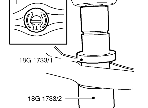
- Position trailing arm, inside face DOWN, on support tool 18G 1733/2 .
- Place NEW bush, with short flange uppermost and the ’LWR’ and arrow markings at the bottom, carefully align the mounting flange faces to centre line of trailing arm.
- Position tool 18G 1733/1 over bush.
- Press bush into arm until tool abuts outside face of trailing arm.
- Fit rear trailing arm assembly. See this section.
REAR ANTI-ROLL BAR
Service repair no - 64.35.08
Remove
- Raise front of vehicle.
WARNING: Support on safety stands.
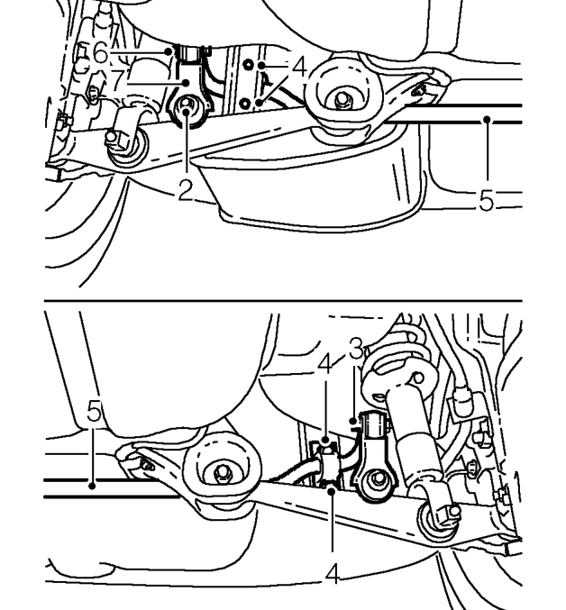
- Remove bolt securing RH stabilising link to lower arm.
- Remove bolt securing LH stabilising link to anti-roll bar.
- Remove 4 bolts securing 2 anti-roll bar bush clamps to mounting brackets.
- Remove anti-roll bar. Do not carry out further dismantling if component is removed for access only.
- Remove bolt securing RH stabilising link to anti-roll bar.
- Remove RH stabilising link.
Parts & tools for this job For 1995 Rover 400
- TOOLCoil spring compressorSearch: coil spring compressor
- TOOLBall joint separatorSearch: ball joint separator
- PARTRear shock absorbersSearch: Rover 400 1995 rear shock absorbers
Links open Amazon search results in a new tab. As an Amazon Associate I earn from qualifying purchases.