
Remove (page 2 of 3)
- Make
- Rover
- Model
- 600 Rover 600 Repair Manual - Volumes 1 and 2 - 2nd Edition
- Section
- Cylinder block: repairs
EngineRemove · page 2 of 3
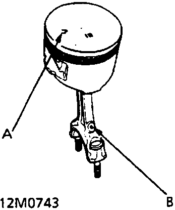
- Use a hydraulic press for installation.
- When pressing the gudgeon pin in or out, be sure to position the recessed flat on the piston against the lugs on the base attachment.
- The arrow on the head of the piston must face the timing belt side of the engine and the connecting rod oil hole must face the rear side of the engine.
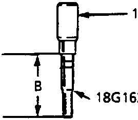
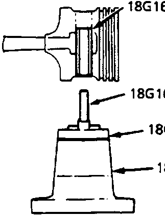
- Adjust the length B of the piston pin driver shaft to 51.5 mm.
- Ensure embossed mark on piston is facing up when pressing in the gudgeon pin.
Note: Install the assembled piston and rod with the oil hole facing the intake manifold.
Parts & tools for this job For Rover 600
- PARTEngine gasket setSearch: Rover 600 engine gasket set
- TOOLTorque wrenchSearch: 3/8 inch torque wrench
- TOOLFeeler gauge setSearch: feeler gauge set
Links open Amazon search results in a new tab. As an Amazon Associate I earn from qualifying purchases.