
Flow meter operation check
- Make
- Fiat
- Model
- 500 Factory Service Manual
- Year
- 2007–2024
- Section
- Diesel injection system › Flow meter operation check
FLOW METER OPERATION CHECK
| STEP | CHECK TO BE PERFORMED | REMEDIAL ACTION IF THE CHECK IS NOT OK |
|---|---|---|
| 1 | Flow meter power supply check Detach the connector attached to the flow meter -Insert disconnector AD 456 n° 1806590000 across the flow meter connector and the wiring connector Connect the positive probe of an Examiner to pin 1 and the negative probe to earth. Turn the ignition key to the MAR position and check that the battery voltage is more than 11 Volts. Move on to Step 2 | Restore the continuity or, if necessary, replace the electrical wiring between the engine control unit and the flow meter See E5050 DIESEL ENGINES ELECTRONIC MANAGEMENT Replace the junction unit Op. 5505A13 |
| 2 | Flow meter earth check Connect the Examiner test probes across pins 1 and 2 of the disconnector Check the voltage is greater than 11 V. Move on to Step 3 | Repair or, if necessary, replace the electrical wiring between the engine management control unit and the flow meter See E5050 DIESEL ENGINES ELECTRONIC MANAGEMENT Replace the engine management control unit |
| 3 | Air flow rate signal check Connect the Examiner in voltmeter mode across pins 4 and 2 of the disconnector Select the following full scale deflection values on the Voltmeter: Voltage 20 Volts f.s.d Time base: 2 secs Press START With the engine idling, check for the presence of an air flow signal as shown in the attached graph. The signal pattern is subordinate to the quantity of air coming into the flow meter. If the air flow is increased, the voltage amplitude does not change significantly but the frequency of the output signal increases | Repair or, if necessary, replace the electrical wiring between the engine management control unit and the flow meter See E5050 DIESEL ENGINES ELECTRONIC MANAGEMENT Check the seal of the flow meter hose, replace the flow meter if it is OK. |
| 4 | Aspirated air temperature signal check Connect the Examiner in voltmeter mode across pins 3 and 2 of the disconnector With the engine idling Press the START button on the voltmeter Check for the presence of an air temperature square-wave signal with a working voltage of 5V and a duty cycle oscillating between 10% (with min. air temperature) and 90% (with max. air temperature), as in the attached graph. | Replace the flow meter |
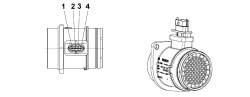
| Flow meter pin out | |
|---|---|
| Pin | Function |
| 1 | +12V power supply |
| 2 | Engine control unit earth |
| 3 | Air temperature output signal |
| 4 | Air flow rate output signal |
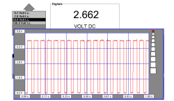
Air temperature signal
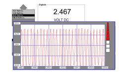
Air flow rate signal
Parts & tools for this job For 2007 Fiat 500
- PARTGlow plugsSearch: Fiat 500 2007 glow plugs
- TOOLGlow plug socketSearch: glow plug socket
- TOOLDiesel compression testerSearch: diesel compression tester
Links open Amazon search results in a new tab. As an Amazon Associate I earn from qualifying purchases.