
Injectors and pipes
- Make
- Fiat
- Model
- 500 Factory Service Manual
- Year
- 2007–2024
- Section
- Diesel injection system › Injectors and pipes
INJECTORS AND PIPES
INJECTORS
The injectors are fitted on the cylinder head and controlled by the injection control unit.
The injector can be divided into two sections:
- actuator/spray consisting of pressure rod (1), pin (2) and nozzle (3);
- control solenoid consisting of coil (4) and pilot valve (5).
Injector operation is divided into three stages.
REST POSTION - the coil (4) is deactivated and the plunger (6) is in the closed position to prevent fuel from being introduced into the cylinder Fc > Fa (Fc: due to line pressure acting on control area 7 of rod 1; Fa: due to line pressure acting on feed volume 8).
START OF INJECTION - the coil (4) is energised and causes the plunger (6) to rise.
Control volume fuel (9) flows out towards the return manifold (10) to bring about a pressure drop on the control area (7). Simultaneously, the line pressure flowing through the intake duct (12) exercises a force Fa > Fc in the supply volume (8) to cause the pin (2) to lift and allow fuel into the cylinders.
END OF INJECTION - the coil (4) is deactivated and causes the plunger (6) to return to closed position. This rebalances the forces so that the pin (2) returns to the closed position and the injection ends.
IMA CLASSIFICATION
During the test stage the injectors are checked with the specifications verified in different pressure/flow rate conditions. All the injectors that do not meet a certain standard are rejected; the remaining ones are classified using a 9 character alphanumerical code, known as an IMA code, imprinted by laser on the top part of the magnet.
During fitting on the vehicle the control unit should memorize the individual code and, if one or more injectors is replaced in a service situation the alteration to the code should be made during the diagnosis using the appropriate equipment.
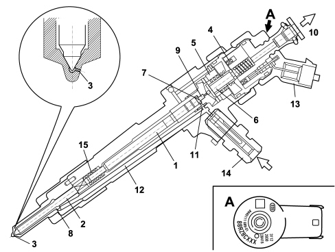
1. Pressure rod
2. Pin
3. Nozzle
4. Coil
5. Pilot valve
6. Ball plunger
7. Control area
8. Feed volume
9. Control volume
10. Fuel return - low pressure
11. Control duct
12. Feed duct
13. Electrical connection
14. Fuel return connector - high pressure
15. Spring
COMMON RAIL
The common rail is fitted to the intake side of the cylinder head.
With a volume of around 20 cm³, this damps fuel pressure fluctuations due to:
- pressure pump operation
- injector opening.
There is a fuel pressure sensor fitted on one side of the supply manifold and the pressure regulator is connected to the other side.
See descriptions 1060G DIESEL INJECTION PRESSURE PUMP ELECTRONIC CONTROL
The hydraulic connections (high pressure) between manifold-pump and manifold-injectors are via steel pipes with a bore of 2 mm and external diameter of 6 mm.
Parts & tools for this job For 2007 Fiat 500
- PARTFuel filterSearch: Fiat 500 2007 fuel filter
- TOOLFuel pressure test kitSearch: fuel pressure test kit
- TOOLFuel line disconnect toolSearch: fuel line disconnect tool
Links open Amazon search results in a new tab. As an Amazon Associate I earn from qualifying purchases.