
Thermostat unit - r+r
- Make
- Fiat
- Model
- 500 Factory Service Manual
- Year
- 2007–2024
- Section
- Engine cooling › Thermostat unit - r+r
THERMOSTAT UNIT - R+R
Removing
- Disconnect the negative battery terminal.
| Description | Connector | |
|---|---|---|
| Battery | See A001 BATTERY |
- Position a suitable container to collect the engine coolant.
Op. 0010T20 ENGINE COOLANT - CHANGE
Op. 5530B52 BATTERY SUPPORT/DRIP TRAY - R.R
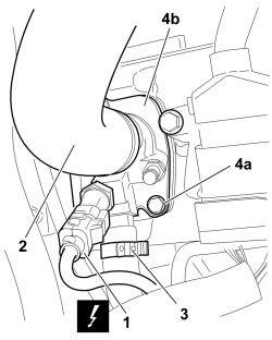
1. Detach the electrical connection for the engine coolant temperature switch.
| Description | Connector | |
|---|---|---|
| 1 | Engine coolant temperature sensor/sender unit | See K036 ENGINE COOLANT TEMPERATURE SENSOR/SENDER UNIT |
2. Open the retaining band and disconnect the engine coolant outlet pipe, thermostat side.
3. Open the retaining band and disconnect the water inlet pipe, thermostat side.
4. Undo retaining bolts (4a) on crankcase, and remove thermostat unit (4b).
Refitting
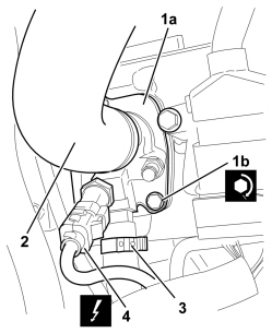
1. Place thermostat unit (1a) in position on the crankcase and tighten retaining bolts (1b) to the recommended torque.
2. Connect the engine coolant outlet pipe, thermostat side, and secure it using the retaining band.
3. Connect the water inlet pipe, thermostat side, and secure it using the retaining band.
4. Connect the electrical connection for the engine coolant temperature switch.
| Description | Connector | |
|---|---|---|
| 4 | Engine coolant temperature sensor/sender unit | See K036 ENGINE COOLANT TEMPERATURE SENSOR/SENDER UNIT |
Op. 5530B52 BATTERY SUPPORT/DRIP TRAY - R.R
- Connect the negative battery terminal.
| Description | Connector | |
|---|---|---|
| Battery | See A001 BATTERY |
Op. 0010T20 ENGINE COOLANT - CHANGE
Removing
- Disconnect the negative battery terminal.
| Description | Connector | |
|---|---|---|
| Battery | See A001 BATTERY |
Op. 0010T20 ENGINE COOLANT - CHANGE
Op. 5530B52 BATTERY SUPPORT/DRIP TRAY - R.R
Op. 1048A10 AIR FILTER ASSEMBLY - R.R.
Op. 1048A23 COLD AIR INTAKE FOR AIR FILTER - R.R
Op. 1048A50 TURBOCHARGER AIR INTAKE PIPE - R.R.
Op. 1048B44 RIGID AIR SUPPLY PIPE BETWEEN HEAT EXCHANGER AND INTAKE MANIFOLD - R.R.
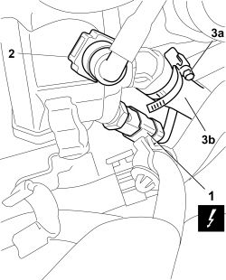
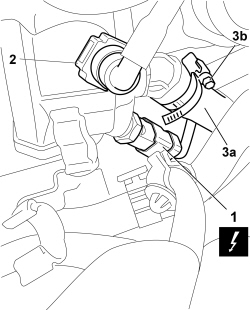
1. Disconnect the electrical connection for the engine coolant temperature sensor/sender unit.
| Description | Connector | |
|---|---|---|
| 1 | Engine coolant temperature sensor/sender unit | See K036 ENGINE COOLANT TEMPERATURE SENSOR/SENDER UNIT |
2. Adjust the quick coupling and disconnect the degassing pipe, thermostat unit side.
3. Open band (3a) and disconnect the sleeve from E.G.R. valve assembly (3b).
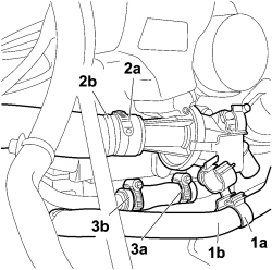
1. Open retaining clip (1a) and place oil vapour recovery pipe (1b) between the separator and the turbocharger to one side
2. Open band (2a) and disconnect engine coolant inlet pipe (2b) to the radiator.
3. Open retaining band (3a) and disconnect coolant supply pipe (3b) to engine oil heat exchanger.
1. Undo bolts (1a) and remove thermostat unit (1b) complete with O-ring.
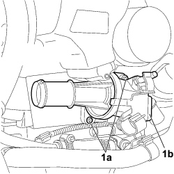
Refitting
1. Place thermostat unit (1a) in its housing with the O-ring and secure it by tightening bolts (1b) to the recommended torque.
| Component | Fastening | dia | Value (daNm) | Validity |
|---|---|---|---|---|
| Thermostat unit (on cylinder head) | Bolt | M8x1.25x22 | 2.5 | 1.3 Multijet |
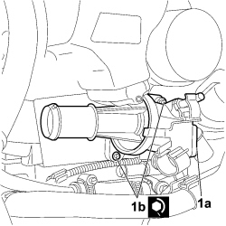
- Connect the coolant supply pipe to the engine oil heat exchanger and attach it with a new retaining band.
- Connect the coolant inlet pipe to the radiator and secure it using a new retaining band.
- Attach the oil vapour recovery pipe between the separator and turbocompressor to the retaining clip.
1. Connect the electrical connection for the engine coolant temperature sensor/sender unit.
| Description | Connector | |
|---|---|---|
| 1 | Engine coolant temperature sensor/sender unit | See K036 ENGINE COOLANT TEMPERATURE SENSOR/SENDER UNIT |
2. Adjust the quick coupling and connect the degassing pipe, thermostat unit side.
3. Connect the sleeve to E.G.R. valve assembly (3a) and secure with new retaining band (3b).
Op. 1048B44 RIGID AIR SUPPLY PIPE BETWEEN HEAT EXCHANGER AND INTAKE MANIFOLD - R.R.
Op. 1048A50 TURBOCHARGER AIR INTAKE PIPE - R.R.
Op. 1048A23 COLD AIR INTAKE FOR AIR FILTER - R.R
Op. 1048A10 AIR FILTER ASSEMBLY - R.R.
Op. 5530B52 BATTERY SUPPORT/DRIP TRAY - R.R
Op. 0010T20 ENGINE COOLANT - CHANGE
- Connect the negative battery terminal.
| Description | Connector | |
|---|---|---|
| Battery | See A001 BATTERY |
Parts & tools for this job For 2007 Fiat 500
- FLUIDCoolantSearch: Fiat coolant antifreeze
- PARTThermostatSearch: Fiat 500 2007 thermostat
- TOOLCooling system pressure testerSearch: cooling system pressure tester
Links open Amazon search results in a new tab. As an Amazon Associate I earn from qualifying purchases.