
System cable loom - r.r.
- Make
- Fiat
- Model
- 500 Factory Service Manual
- Year
- 2007–2024
- Section
- Petrol injection system › System cable loom - r.r.
SYSTEM CABLE LOOM - R.R.
Removing
Op. 1048A23 COLD AIR INTAKE FOR AIR FILTER - R.R
Op. 1048A10 AIR FILTER ASSEMBLY - R.R.
Op. 5530B52 BATTERY SUPPORT/DRIP TRAY - R.R
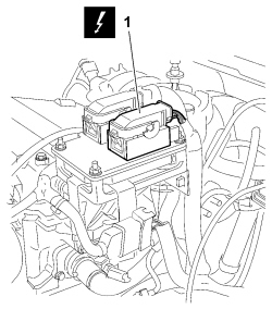
1. Connect the electrical connection for the injection control unit.
| Description | Connector | |
|---|---|---|
| 1 | Injection control unit | See M010 ENGINE MANAGEMENT ECU |
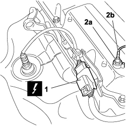
1. Disconnect the electrical connection for the pre-converter Lambda sensor.
| Description | Connector | |
|---|---|---|
| 1 | Pre-converter Lambda sensor | See K015 LAMBDA SENSOR ON PRE-CATALYZER |
2. Undo retaining bolt (2a) for earth lead on engine (2b).
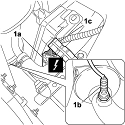
1. Disconnect electrical connection (1a) for converter lambda sensor (1b) and free the wiring looms from retaining clip (1c).
| Description | Connector | |
|---|---|---|
| 1a | Converter lambda sensor | See K017 LAMBDA SENSOR ON CATALYZER |
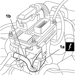
1. Disconnect front/engine electrical coupling (1a) and free wiring loom (1b) from the retaining clip.
| Description | Connector | |
|---|---|---|
| 1a | Front/engine coupling | See D004 FRONT/ENGINE COUPLING |
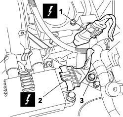
1. Disconnect the injector electrical coupling, freeing the wiring loom from the retaining clip
| Description | Connector | |
|---|---|---|
| 1 | Injector coupling | See D081 INJECTOR JUNCTION |
2. Disconnect the ignition coil electrical connection.
| Description | Connector | |
|---|---|---|
| 2 | Ignition coil | See A030 IGNITION COIL |
3. Undo the retaining bolt for the injection control unit wiring loom mount.
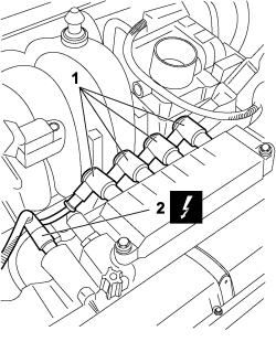
1. Disconnect the spark plug electrical connections, coil/ignition coil side.
2. Disconnect the electrical connection for the variable valve timing electromagnet
| Description | Connector | |
|---|---|---|
| 2 | Variable valve timing electromagnet | See K098 PHASE TRANSFORMER SOLENOID |
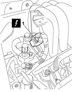
1. Disconnect the electrical connection for the aspirated air temperature/pressure sensor.
| Description | Connector | |
|---|---|---|
| 1 | Air pressure - temperature sensor | See K044 AIR TEMPERATURE/PRESSURE SENSOR |
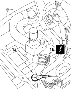
1. Undo retaining bolt (1a) and disconnect earth lead on compressor (1b).
| Description | Connector | |
|---|---|---|
| 1b | Earth on compressor | See C039 COMPRESSOR EARTH |
1. Disconnect electrical connection (1a) for throttle body actuator and free wiring loom from retaining clips (1b).
| Description | Connector | |
|---|---|---|
| 1a | Throttle body actuator | See N075 BUILT-IN THROTTLE BODY ACTUATOR |
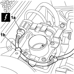
1. Disconnect the electrical connection for timing sensor (1a) and for engine coolant temperature sensor/transmitter (1b).
| Description | Connector | |
|---|---|---|
| 1a | Timing sensor | See K047 TIMING SENSOR |
| Description | Connector | |
|---|---|---|
| 1b | Engine coolant temperature sensor/sender unit | See K036 ENGINE COOLANT TEMPERATURE SENSOR/SENDER UNIT |
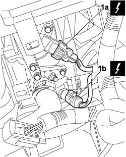
1. Disconnect the electrical connection for the fuel vapour recovery enablement solenoid.
| Description | Connector | |
|---|---|---|
| 1 | Fuel vapour recovery solenoid valve | See L010 FUEL VAPOUR RECOVERY SOLENOID VALVE |
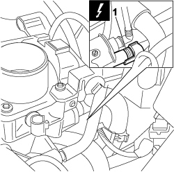
- Loosen the fastenings on the timing belt upper cover and release the wiring loom of the rpm sensor and the engine oil pressure switch.
- Position the vehicle on a lift.
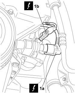
1. Disconnect the electrical connection for engine rpm sensor (1a) and for insufficient engine oil pressure sensor/switch (1b).
| Description | Connector | |
|---|---|---|
| 1a | Engine rpm sensor | See K046 RPM SENSOR |
| Description | Connector | |
|---|---|---|
| 1b | Insufficient engine oil pressure sensor/switch | See K030 ENGINE OIL PRESSURE SENSOR (SWITCH) |
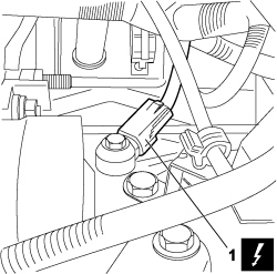
1. Disconnect the electrical connection for the knock sensor.
| Description | Connector | |
|---|---|---|
| 1 | Knock sensor | See K050 DETONATION SENSOR |
The knock sensor is located on the rear of the engine under the intake manifold.
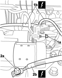
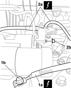
1. Undo retaining nut (1a) and diconnect starter motor electrical leads (1b).
| Description | Connector | |
|---|---|---|
| 1b | Starter motor | See A020 STARTER MOTOR |
2. Undo retaining bolt (2a) and disconnect engine earth lead (2b).
| Description | Connector | |
|---|---|---|
| 2b | Earth on engine | See C040 ENGINE EARTH |
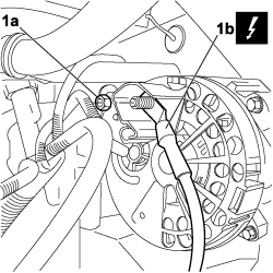
1. Undo nut (1a) and disconnect electrical cable (1b) from the alternator.
| Description | Connector | |
|---|---|---|
| 1b | Alternator | See A010 ALTERNATOR |
- Remove the wiring loom assembly.
Refitting
- Check the condition of the electrical wiring.
- If required, test the continuity of individual connectors.
1. Connect alternator electrical cable (1a) and tighten nut (1b) to the recommended torque.
| Description | Connector | |
|---|---|---|
| 1a | Alternator | See A010 ALTERNATOR |
| Component | Fastening | dia | Value (daNm) | Validity |
|---|---|---|---|---|
| B+ recharging lead (on alternator) | Nut | M8 | 0.9 | all versions |
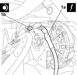
1. Position the earth lead on engine (1a) and tighten bolt (1b).
| Description | Connector | |
|---|---|---|
| 1a | Earth on engine | See C040 ENGINE EARTH |
2. Connect starter motor (2a) electrical cables and tighten nut (2b).
| Description | Connector | |
|---|---|---|
| 2a | Starter motor | See A020 STARTER MOTOR |
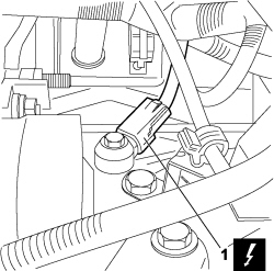
1. Connect the electrical connection for the knock sensor.
The knock sensor is located on the rear of the engine under the intake manifold.
| Description | Connector | |
|---|---|---|
| 1 | Knock sensor | See K050 DETONATION SENSOR |
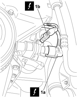
1. Connect the electrical connection for engine rpm sensor (1a) and for insufficient engine oil pressure sensor/switch (1b).
| Description | Connector | |
|---|---|---|
| 1a | Engine rpm sensor | See K046 RPM SENSOR |
| Description | Connector | |
|---|---|---|
| 1b | Insufficient engine oil pressure sensor/switch | See K030 ENGINE OIL PRESSURE SENSOR (SWITCH) |
- Lower the vehicle.
- Restore the wiring loom of the engine rpm sensor and of the engine oil insufficient pressure switch/sensor and tighten the fastenings of the timing belt upper cover.
1. Connect the electrical connection of the fuel vapour recovery enablement solenoid valve.
| Description | Connector | |
|---|---|---|
| 1 | Fuel vapour recovery solenoid valve | See L010 FUEL VAPOUR RECOVERY SOLENOID VALVE |
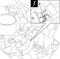
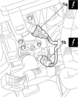
1. Connect the electrical connection for timing sensor (1a) and for engine coolant temperature sensor/transmitter (1b).
| Description | Connector | |
|---|---|---|
| 1a | Timing sensor | See K047 TIMING SENSOR |
| Description | Connector | |
|---|---|---|
| 1b | Engine coolant temperature sensor/sender unit | See K036 ENGINE COOLANT TEMPERATURE SENSOR/SENDER UNIT |
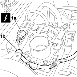
1. Connect electrical connection (1a) of throttle body actuator and attach the wiring loom to retaining clips (1b).
| Description | Connector | |
|---|---|---|
| 1a | Throttle body actuator | See N075 BUILT-IN THROTTLE BODY ACTUATOR |
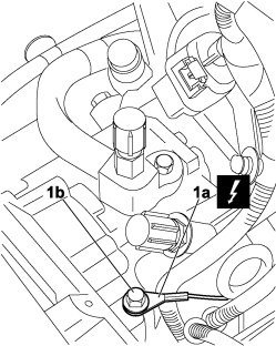
1. Position the earth lead on compressor (1a) and tighten bolt (1b).
| Description | Connector | |
|---|---|---|
| 1a | Earth on compressor | See C039 COMPRESSOR EARTH |
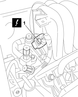
1.Connect the electrical connection for the aspirated air temperature/pressure sensor.
| Description | Connector | |
|---|---|---|
| 1 | Air pressure - temperature sensor | See K044 AIR TEMPERATURE/PRESSURE SENSOR |
1. Connect the spark plug electrical connections, coil/ignition coil side.
2. Connect the electrical connection for the variable valve timing solenoid.
| Description | Connector | |
|---|---|---|
| 2 | Variable valve timing electromagnet | See K098 PHASE TRANSFORMER SOLENOID |
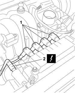
1. Connect the injector electrical coupling, attaching the wiring loom to the retaining clip.
| Description | Connector | |
|---|---|---|
| 1 | Injector coupling | See D081 INJECTOR JUNCTION |
2. Connect the ignition coil electrical connection.
| Description | Connector | |
|---|---|---|
| 2 | Ignition coil | See A030 IGNITION COIL |
3. Tighten the retaining bolt for the injection control unit wiring loom mount.
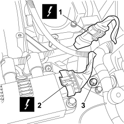
1. Connect front/engine electrical coupling (1a) and attach wiring loom (1b) to the retaining clip.
| Description | Connector | |
|---|---|---|
| 1a | Front/engine coupling | See D004 FRONT/ENGINE COUPLING |
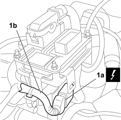
1. Connect electrical connection (1a) of converter lambda sensor (1b) and attach the wiring loom to retaining clip (1c).
| Description | Connector | |
|---|---|---|
| 1a | Converter lambda sensor | See K017 LAMBDA SENSOR ON CATALYZER |
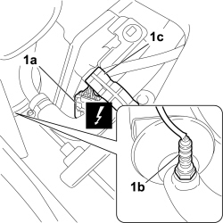
1. Connect the electrical connection for the pre-converter Lambda sensor.
| Description | Connector | |
|---|---|---|
| 1 | Pre-converter Lambda sensor | See K015 LAMBDA SENSOR ON PRE-CATALYZER |
2. Position the earth lead on engine (2a) and tighten bolt (2b).
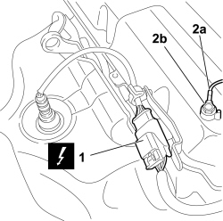
1. Connect the electrical connection for the injection control unit
| Description | Connector | |
|---|---|---|
| 1 | Injection control unit | See M010 ENGINE MANAGEMENT ECU |
Op. 5530B52 BATTERY SUPPORT/DRIP TRAY - R.R
Op. 1048A10 AIR FILTER ASSEMBLY - R.R.
Op. 1048A23 COLD AIR INTAKE FOR AIR FILTER - R.R
Removing
- Position the vehicle on a lift.
- Disconnect the negative battery terminal.
| Description | Connector | |
|---|---|---|
| Battery | See A001 BATTERY |
Op. 1048A23 COLD AIR INTAKE FOR AIR FILTER - R.R
Op. 1048A10 AIR FILTER ASSEMBLY - R.R.
Op. 1048A32 HOSE FROM AIR FILTER TO INTAKE MANIFOLD - R + R
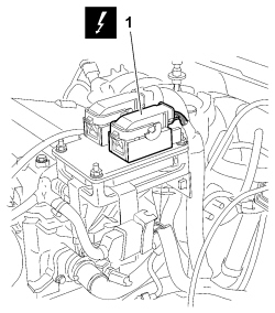
1. Disconnect the electrical connection for the engine management control unit, releasing the cable loom from the retaining clips.
| Description | Connector | |
|---|---|---|
| 1 | Engine management control unit | See M010 ENGINE MANAGEMENT ECU |
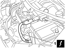
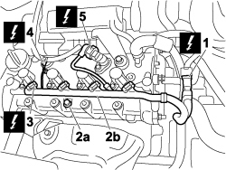
1. Disconnect the electrical coupling between the engine wiring and the front wiring.
| Description | Connector | |
|---|---|---|
| 1 | Front/engine coupling | See D004 FRONT/ENGINE COUPLING |
2. Undo the bolt (2a) securing the injector wiring duct (2b).
3. Disconnect all the electrical connections for the ignition coils.
| Description | Connector | |
|---|---|---|
| 3 | Ignition coil | See A030 IGNITION COIL |
4. Undo the nut and disconnect the engine earth lead.
| Description | Connector | |
|---|---|---|
| 4 | Earth on engine | See C040 ENGINE EARTH |
5. Detach the timing sensor electrical connection.
| Description | Connector | |
|---|---|---|
| 5 | Timing sensor | See K047 TIMING SENSOR |
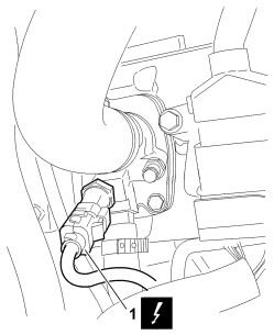
1. Disconnect the electrical connection for the engine coolant temperature sensor.
| Description | Connector | |
|---|---|---|
| 1 | Engine coolant temperature sensor/sender unit | See K036 ENGINE COOLANT TEMPERATURE SENSOR/SENDER UNIT |
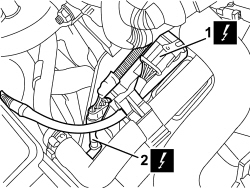
1. Disconnect the electrical connection for the upper Lambda sensor.
| Description | Connector | |
|---|---|---|
| 1 | Lambda sensor on pre-catalyzer | See K015 LAMBDA SENSOR ON PRE-CATALYZER |
2. Disconnect the electrical connection for the lower Lambda sensor.
| Description | Connector | |
|---|---|---|
| 2 | Lambda sensor on catalytic converter | See K017 LAMBDA SENSOR ON CATALYZER |
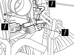
1. Disconnect the electrical connection for the fuel vapour flow enablement solenoid valve.
| Description | Connector | |
|---|---|---|
| 1 | Fuel vapour recovery solenoid valve | See L010 FUEL VAPOUR RECOVERY SOLENOID VALVE |
2. Disconnect the electrical connection for the throttle casing actuator.
| Description | Connector | |
|---|---|---|
| 2 | Integrated throttle body actuator | See N075 BUILT-IN THROTTLE BODY ACTUATOR |
3. Disconnect the injector electrical coupling.
| Description | Connector | |
|---|---|---|
| 3 | Injector coupling | See D081 INJECTOR JUNCTION |
4. Release the wiring from the retaining clip.
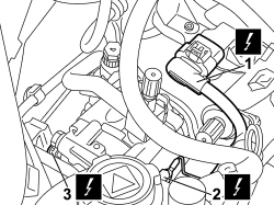
1. Disconnect the electrical connection for the intake air temperature sensor.
| Description | Connector | |
|---|---|---|
| 1 | Air pressure - temperature sensor | See K044 AIR TEMPERATURE/PRESSURE SENSOR |
2. Undo the fixing bolt and disconnect the earth lead on the compressor.
| Description | Connector | |
|---|---|---|
| 2 | Compressor earth | See C039 COMPRESSOR EARTH |
3. Disconnect the compressor engagement electromagnet electrical connection.
| Description | Connector | |
|---|---|---|
| 3 | Air conditioning compressor engagement electro-magnet | See L020 AIR CONDITIONING COMPRESSOR ENGAGEMENT ELECTRO-MAGNET |
1. Disconnect the electrical connection for the engine oil pressure switch.
| Description | Connector | |
|---|---|---|
| 1 | Insufficient engine oil pressure sensor (switch) | See K030 ENGINE OIL PRESSURE SENSOR (SWITCH) |
2. Detach the rpm sensor electrical connection.
| Description | Connector | |
|---|---|---|
| 2 | Rpm sensor | See K046 RPM SENSOR |
- Release the electrical wiring from its seat on the timing belt protective covers.
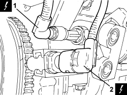
1. Disconnect the electrical connection for the knock sensor.
| Description | Connector | |
|---|---|---|
| 1 | Knock sensor | See K050 DETONATION SENSOR |
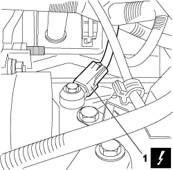
- Remove the cable loom.
Refitting
- Check the condition of the electrical wiring.
- If appropriate, carry out the continuity test on the individual connectors.
1. Connect the electrical connection for the detonation sensor.
| Description | Connector | |
|---|---|---|
| 1 | Knock sensor | See K050 DETONATION SENSOR |
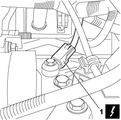
1. Connect the electrical connection for the engine oil pressure switch.
| Description | Connector | |
|---|---|---|
| 1 | Insufficient engine oil pressure sensor (switch) | See K030 ENGINE OIL PRESSURE SENSOR (SWITCH) |
2. Connect the electrical connection for the rpm sensor.
| Description | Connector | |
|---|---|---|
| 2 | Rpm sensor | See K046 RPM SENSOR |
- Restore the electrical wiring in its seat on the timing belt protective covers.
1. Connect the electrical connection for the intake air temperature sensor.
| Description | Connector | |
|---|---|---|
| 1 | Air pressure - temperature sensor | See K044 AIR TEMPERATURE/PRESSURE SENSOR |
2. Position the earth leadon the compressor and tighten the bolt.
| Description | Connector | |
|---|---|---|
| 2 | Compressor earth | See C039 COMPRESSOR EARTH |
3. Connect the electrical connection for the compressor engagement electromagnet.
| Description | Connector | |
|---|---|---|
| 3 | Air conditioning compressor engagement electro-magnet | See L020 AIR CONDITIONING COMPRESSOR ENGAGEMENT ELECTRO-MAGNET |
1. Connect the electrical connection for the fuel vapour flow enablement solenoid valve.
| Description | Connector | |
|---|---|---|
| 1 | Fuel vapour recovery solenoid valve | See L010 FUEL VAPOUR RECOVERY SOLENOID VALVE |
2. Connect the electrical connection for the throttle casing actuator.
| Description | Connector | |
|---|---|---|
| 2 | Integrated throttle body actuator | See N075 BUILT-IN THROTTLE BODY ACTUATOR |
3. Connect the injector electrical coupling.
| Description | Connector | |
|---|---|---|
| 3 | Injector coupling | See D081 INJECTOR JUNCTION |
4. Secure the wiring to the retaining clip.
1. Connect the electrical connection for the upper Lambda sensor.
| Description | Connector | |
|---|---|---|
| 1 | Lambda sensor on pre-catalyzer | See K015 LAMBDA SENSOR ON PRE-CATALYZER |
2. Connect the electrical connection for the lower Lambda sensor.
| Description | Connector | |
|---|---|---|
| 2 | Lambda sensor on catalytic converter | See K017 LAMBDA SENSOR ON CATALYZER |
1. Connect the electrical connection for the engine coolant temperature sensor.
| Description | Connector | |
|---|---|---|
| 1 | Engine coolant temperature sensor/sender unit | See K036 ENGINE COOLANT TEMPERATURE SENSOR/SENDER UNIT |
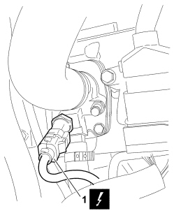
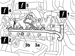
1. Connect the electrical coupling between the engine wiring and the front wiring.
| Description | Connector | |
|---|---|---|
| 1 | Front/engine coupling | See D004 FRONT/ENGINE COUPLING |
2. Disconnect all the electrical connections for the ignition coils.
| Description | Connector | |
|---|---|---|
| 2 | Ignition coil | See A030 IGNITION COIL |
3. Position the injector wiring duct (3a) and tighten the fixing bolt (3b).
4. Position the earth lead on the engine and tighten the bolt.
| Description | Connector | |
|---|---|---|
| 4 | Earth on engine | See C040 ENGINE EARTH |
5. Connect the electrical connection for the timing sensor.
| Description | Connector | |
|---|---|---|
| 5 | Timing sensor | See K047 TIMING SENSOR |
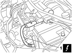
1. Connect the electrical connection for the engine management control unit, securing the cable loom to the retaining clips.
| Description | Connector | |
|---|---|---|
| 1 | Engine management control unit | See M010 ENGINE MANAGEMENT ECU |
Op. 1048A32 HOSE FROM AIR FILTER TO INTAKE MANIFOLD - R + R
Op. 1048A10 AIR FILTER ASSEMBLY - R.R.
Op. 1048A23 COLD AIR INTAKE FOR AIR FILTER - R.R
- Connect the negative battery terminal.
| Description | Connector | |
|---|---|---|
| Battery | See A001 BATTERY |
- Remove the vehicle from the lift.
Parts & tools for this job For 2007 Fiat 500
- PARTEngine gasket setSearch: Fiat 500 2007 engine gasket set
- TOOLTorque wrenchSearch: 3/8 inch torque wrench
- TOOLFeeler gauge setSearch: feeler gauge set
Links open Amazon search results in a new tab. As an Amazon Associate I earn from qualifying purchases.