
Pistons, connecting rods and cylinder bores
- Make
- Land Rover
- Model
- Discovery II (UK)
- Section
- Overhaul › Pistons, connecting rods and cylinder bores
Engine - Td5Pistons, connecting rods and cylinder bores · page 1 of 2
Inspect
Pistons, connecting rods and cylinder bores
$% 12.17.02.03
Disassembly
- Remove cylinder head gasket. ENGINE - Td5, OVERHAUL, Gasket - cylinder head.
- Remove connecting rod bearings. ENGINE - Td5, OVERHAUL, Bearings - connecting rods.
- Remove ridge of carbon from top of cylinder bore.
- Suitably identify each piston and connecting rod assembly to its respective cylinder bore.
- Carefully push connecting rod to top of cylinder bore taking care that connecting rod does not contact oil squirt jet or cylinder wall; remove each piston and connecting rod in turn.
- Using a suitable expander, remove and discard piston rings from pistons.
- Clean carbon from piston crown and skirt. Do not use abrasives on graphited area of piston skirt, do not use a wire brush or scraper on any part of pistons.
- Secure connecting rod in a soft jawed vice.
- Suitably identify each piston to its connecting rod and fitted position of piston on rod.
- Using suitable circlip pliers, remove and discard 2 circlips securing gudgeon pin.
- Push gudgeon pin out of piston and connecting rod; remove piston.
- Suitably identify each gudgeon pin to its respective piston.
- Repeat above procedures for remaining pistons.
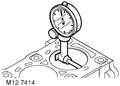
- Measure cylinder bore for wear at a point 70 mm (2.75 in) from top of cylinder bore: Measurement must be taken from side to side and front to rear. l Cylinder bore diameter = 84.460 to 84.442 mm (3.325 to 3.324 in)
CAUTION: Cylinder bore and ovality must be within the limits given above, no reboring, honing or de-glazing of cylinder bores is permissible; cylinder block must be replaced if bores are worn or excessively scored.
- Check piston for cracks, burning and damage.
- Check connecting rods for alignment. Do not attempt to straighten misaligned connecting rods. Ensure small-end lubrication holes in connecting rods are clear.
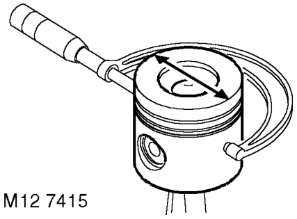
- Measure and record diameter of each piston at right angles to gudgeon pin axis and 46 mm (1.81 in) from bottom of skirt l Piston diameter = 84.262 mm ± 0.009 mm (3.317 in ± 0.0003 in)
CAUTION: Measurement point must be on the ungraphited area of the piston.
Parts & tools for this job For Land Rover Discovery
- PARTEngine gasket setSearch: Land Rover Discovery engine gasket set
- TOOLTorque wrenchSearch: 3/8 inch torque wrench
- TOOLFeeler gauge setSearch: feeler gauge set
Links open Amazon search results in a new tab. As an Amazon Associate I earn from qualifying purchases.