
57M0126 (page 2 of 2)
- Make
- Rover
- Model
- 600 Rover 600 Repair Manual - Volumes 1 and 2 - 2nd Edition
- Section
- Repairs
Steering57M0126 · page 2 of 2
- Coat the pump housing groove with power steering fluid, then position a new housing seal on the pump housing.
- Coat the new plunger seal with power steering fluid, install it over the plungers.
- Install the dowel pins in the pump housing.
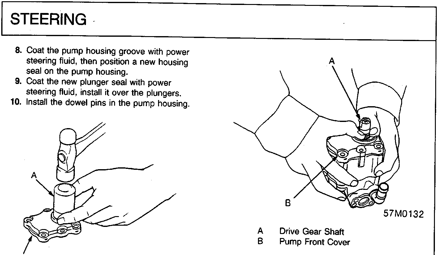
A Socket (OD 36 mm)
B Pump Front Cover
- Install the new oil seal in the pump front cover; get it started by hand, then use a socket to push it in the rest of the way.
- Coat the lip of the seal with steering grease.
A Drive Gear Shaft
B Vinyl Tape
- Wrap the splined area of the drive gear shaft with vinyl tape and grease the surface of the tape.
A Drive Gear Shaft
B Pump Front Cover
- Slide the pump front cover over the drive gear shaft, being careful not to damage the sealing lip or dislodge the spring of the oil seal, then remove the vinyl tape.
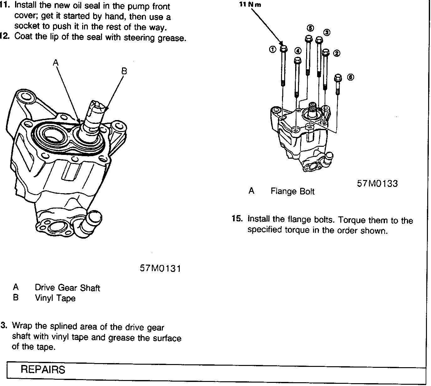
11 Nm
A Flange Bolt
- Install the flange bolts. Torque them to the specified torque in the order shown.
Parts & tools for this job For Rover 600
- TOOLTie rod end toolSearch: tie rod end puller
- TOOLBall joint separatorSearch: ball joint separator
- FLUIDPower steering fluidSearch: Rover power steering fluid
Links open Amazon search results in a new tab. As an Amazon Associate I earn from qualifying purchases.