
Engine management system - MEMS (Relays): Description and operation
- Make
- Rover
- Model
- 800 Workshop Manual
- Year
- 1996–1999
- Section
- Description and operation › Relays
Relays
Main relay engine management: Energised when the ignition is switched on and supplies current to the ECM, injectors, idle air control valve (KV6), stepper motor (’T’ series), heated oxygen sensor, fan relay and VIS valves (KV6).
Fuel pump relay: Energised by the ECM for a short period when the ignition is switched on, during cranking and while the engine is running.
Starter relay: Energised by the cranking signal from the ignition switch.
Inertia switch
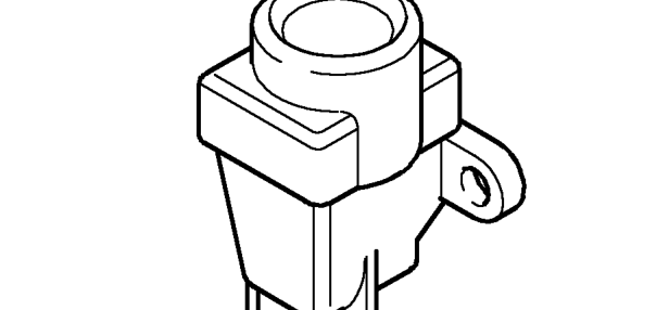
The fuel pump circuit incorporates an inertia switch which in the event of sudden deceleration isolates the power supply to the fuel pump. The inertia switch is situated in the engine compartment on the RH side of the bulkhead and can, if tripped, be reset by depressing the central plunger.
WARNING: Check the integrity of the fuel system before the inertia switch is reset.
TestBook connector
A TestBook connector is provided to enable diagnosis to be carried out without disturbing the system electrical connections and to allow the ECM’s ability to store certain faults to be utilised.
AIR FLOW SYSTEM - KV6
Inlet air is drawn through an air filter element into the siamesed throttle housing. Incorporated in the throttle housing are the twin throttle disc’s, idle air control valve and the throttle position sensor (potentiometer).
Air is passed from the throttle housing via the inlet chambers to the individual inlet manifolds where the injectors inject the fuel before the mixture is drawn into the combustion chambers.
A load signal, from the manifold absolute pressure sensor, is applied to the ECM from the inlet chamber. This signal along with that supplied by the inlet air temperature sensor is used to calculate the fuel delivery to the injectors.
Parts & tools for this job For 1996 Rover 800
- TOOLDigital multimeterSearch: automotive digital multimeter
- PARTAssorted fuse kitSearch: car fuse assortment kit
- TOOLWire crimper and connector kitSearch: wire crimper connector kit
Links open Amazon search results in a new tab. As an Amazon Associate I earn from qualifying purchases.