
Header rail – Adjust
- Make
- Rover
- Model
- Coupé, Cabriolet & Tourer 200/400 Coupé, Cabriolet & Tourer Workshop Manual
- Section
- Hood › Header rail – Adjust
BodyHeader rail – Adjust
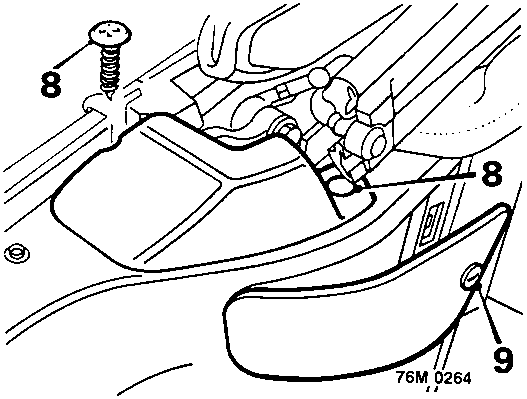
- Remove screw and trim stud from each hood hinge cover and remove hinge covers.
- Release turnbuckles on hood strut inspection covers and remove covers.
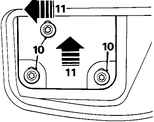
- Slacken hood hinge bracket fixings (TX40 Torx bit).
- With assistance, lift each hood hinge up and forward as far as possible before tightening screws.
CAUTION: Do not raise hood before brackets are tightened, or serious damage may result. If hood hinge brackets are incorrectly set, hood will foul on rear windows, again resulting in serious damage.
- Raise hood onto 50mm deep wooden blocks placed on the top of each 'B' post.
- Fit Belville washer to inside of each strut trunnion before fitting clevis pins and retaining clips.
- Fit wire hook to front headlining straps.
- Reach between hood strut and rear quarter trim panel and engage headlining strap hook into its bracket at base of hood strut.
- Fit headlining tension rods and engage elastic straps over the end of each rod.
CAUTION: The tension rods are 'handed' and will not lie flat on rear shelf if fitted incorrectly.
- Engage the end of each tension rod in its location and align fixing hole with a bradawl before fitting screw.
- Secure velcro on headlining to sides of backlight and rear shelf trim.
- Remove blocks from 'B' posts.
Note: If header rail adjustment is not necessary, proceed to item 27.
Header rail – Adjust
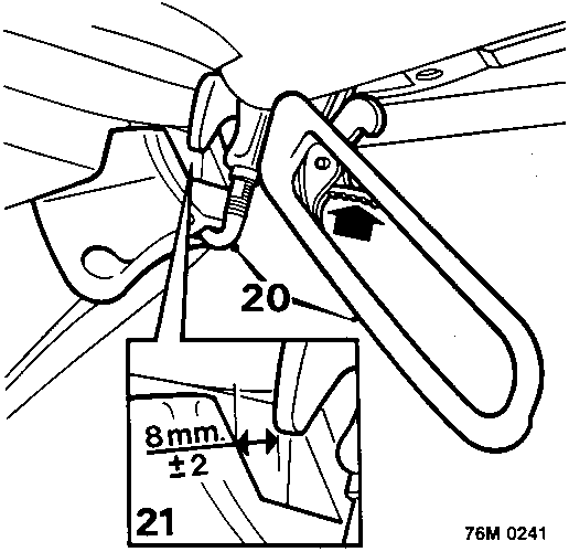
- Engage hood handle hooks into 'A' post locations, leaving handles in 'unlocked' (lowered) position.
- Measure distance between hood header location pins and plastic striker plates set into 'A' posts. This should be 8mm ± 2mm.
- Adjustment as necessary: release hooks from 'A' posts and fully lower hood.
CAUTION: The hood must be in lowered position before header is adjusted as this relieves tension from hood frame cables.
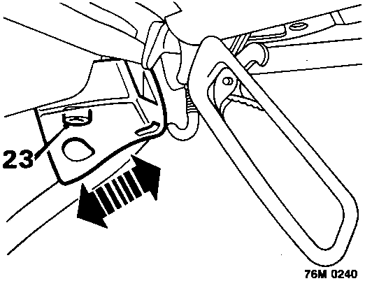
- Slacken header securing bolts and adjust position of header.
- Tighten header securing bolts and raise hood.
- Engage hooks in 'A' post locations, but leave handles in 'unlocked' position.
- Check for correct gap between header locating pins and plastic striker plates. Adjust if necessary, ensuring that hood is fully lowered before header mounting bolts are slackened.
Parts & tools for this job For Rover Coupé, Cabriolet & Tourer
- TOOLTrim removal tool kitSearch: trim removal tool kit
- PARTTouch-up paintSearch: Rover touch up paint
- PARTPanel clip assortmentSearch: Rover panel clips assortment
Links open Amazon search results in a new tab. As an Amazon Associate I earn from qualifying purchases.