
Hood frame – cabriolet
- Make
- Rover
- Model
- Coupé, Cabriolet & Tourer 200/400 Coupé, Cabriolet & Tourer Workshop Manual
- Section
- Hood › Hood frame – cabriolet
BodyHood frame – cabriolet
- Fit headlining tension rods and engage elastic straps over the end of each rod.
CAUTION: The tension rods are 'handed' and will not lie flat on rear shelf if fitted incorrectly.
- Engage the end of each tension rod in its location and align fixing hole with a bradawl before fitting screw.
- Secure Velcro on headlining to sides of backlight and rear shelf trim.
- Remove support blocks from hood frame.
- Adjust cantrail cable tension, see Cantrail cable tension – check and adjust.
HOOD FRAME – CABRIOLET
Service Repair No. 76.61.12
The following operation involves the bonding of fabric backed vinyl to various steel components of the hood frame. If adhesive is to be applied to the fabric backing, Dunlop 758 adhesive or equivalent should be used. For direct application on vinyl surfaces, use Dunlop S1588 adhesive or equivalent.
A thin coating of adhesive should be applied to both surfaces and then allowed to cure, until just touch dry, for between 5 and 10 minutes, before the bond is made.
Remove
Power Hood
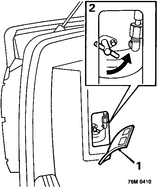
- Open boot and remove inspection cover from hood pump.
- Turn isolator valve anti - clockwise through at least four turns to isolate hood rams.
All Models
- Lower both rear windows.
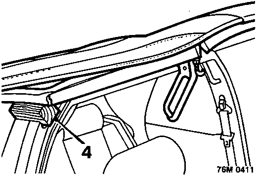
- Lift hood slightly to allow a 50 mm deep support block to be placed between top of each 'B' post and underside of hood frame.
Parts & tools for this job For Rover Coupé, Cabriolet & Tourer
- TOOLTrim removal tool kitSearch: trim removal tool kit
- PARTTouch-up paintSearch: Rover touch up paint
- PARTPanel clip assortmentSearch: Rover panel clips assortment
Links open Amazon search results in a new tab. As an Amazon Associate I earn from qualifying purchases.