
Power hood ram – cabriolet
- Make
- Rover
- Model
- Coupé, Cabriolet & Tourer 200/400 Coupé, Cabriolet & Tourer Workshop Manual
- Section
- Hood › Power hood ram – cabriolet
BodyPower hood ram – cabriolet
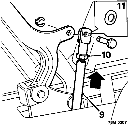
- Lift hood rams to their fully extended positions.
WARNING: To avoid personal injury and damage to hood, do not operate rams hydraulically before hood is fully assembled.
- Check for exact alignment of clevis pin holes in ram trunnion and hood. If adjustment is necessary, loosen trunnion lock nut and rotate trunnion until holes are exactly aligned.
- Fit a Belville washer in one side of each trunnion before fitting clevis pin and retaining clip.
- Remove support block from header rail and position two 50mm deep blocks on 'B' posts.
- Fit wire hook to front headlining straps.
- Reach between hood ram and rear quarter trim panel and engage headlining strap hook into its bracket at base of hood ram.
- Thread elastic straps at rear of headlining through hooks in backlight lower rail.
- Fit headlining tension rods and engage elastic straps over end of each rod.
CAUTION: Tension rods are 'handed' and will not lie flat on rear shelf if fitted incorrectly.
- Engage end of each tension rod in its location and align fixing hole with a bradawl, or similar tool, before fitting screw.
- Secure Velcro on headlining to sides of backlight and rear shelf trim.
- Remove wooden support blocks from 'B' posts.
- Adjust hood header rail, see Adjustments – Power hood adjust Cabriolet.
- Fit hood hinge covers and secure with fixing stud and screw.
- Turn hood pump isolator valve fully clockwise and replace inspection cover.
- Check for correct operation of hood.
POWER HOOD RAM – CABRIOLET
Service Repair No. 76.61.65
Remove
- Lower hood.
- Remove rear seat cushion and squabs, see Rear seat squabs and cushion – Cabriolet/Coupe.
- Remove rear quarter trim panel, see Rear quarter trim panel – Cabriolet.
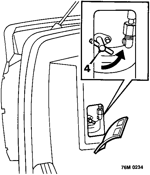
- Remove hood pump inspection cover and turn isolator valve at least 4 full turns anti – clockwise to isolate rams.
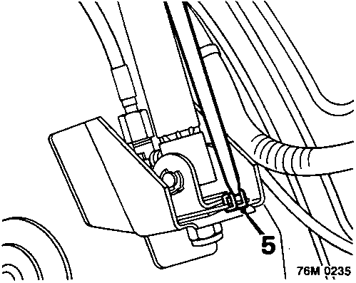
- Disengage elastic headlining strap from its location at base of hood ram and remove wire clip from elastic strap.
Parts & tools for this job For Rover Coupé, Cabriolet & Tourer
- TOOLTrim removal tool kitSearch: trim removal tool kit
- PARTTouch-up paintSearch: Rover touch up paint
- PARTPanel clip assortmentSearch: Rover panel clips assortment
Links open Amazon search results in a new tab. As an Amazon Associate I earn from qualifying purchases.