
Cantrail cable tension – check and adjust – cabriolet
- Make
- Rover
- Model
- Coupé, Cabriolet & Tourer 200/400 Coupé, Cabriolet & Tourer Workshop Manual
- Section
- Hood › Cantrail cable tension – check and adjust – cabriolet
BodyCantrail cable tension – check and adjust – cabriolet
CANTRAIL CABLE TENSION – CHECK AND ADJUST – CABRIOLET
Service Repair No. 76.61.25
Check
- Raise hood and secure handles.
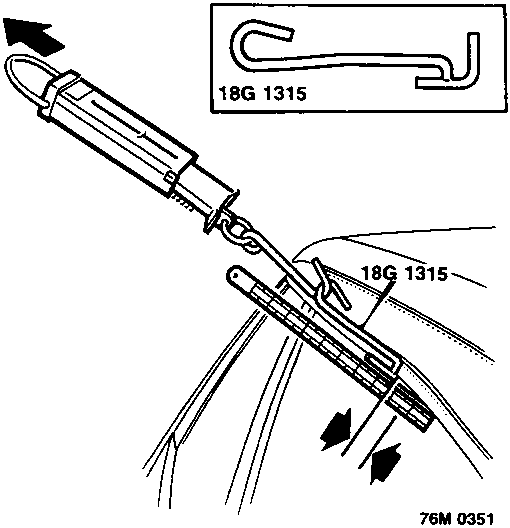
- Check cable tension by applying 2 Kg pull at centre of cantrail using tool 18G 1315 and a spring balance. Edge of outer covering should deflect by between 6 and 9mm. Ensure balance is held at angle shown and rule is held steady against window glass whilst measurement is taken.
Adjust
- Lower rear windows, one turn of handle.
- Lower hood partially until forward half is positioned vertically.
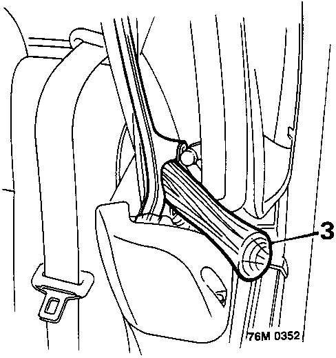
- Power hood: Place chocks in both sides of hood mechanism.
Header rail – Adjust
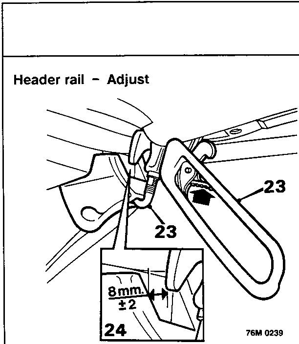
- Engage hood handle hooks into ‘A’ post locations, leaving handles in ‘unlocked’ position.
- Measure distance between hood header location pins and plastic striker plates set into ‘A’ posts. This should be 8mm ± 2mm.
- Adjust as necessary: release hooks from ‘A’ posts and fully lower hood.
CAUTION: The hood must be in lowered position before header is adjusted as this relieves tension from hood frame cables.
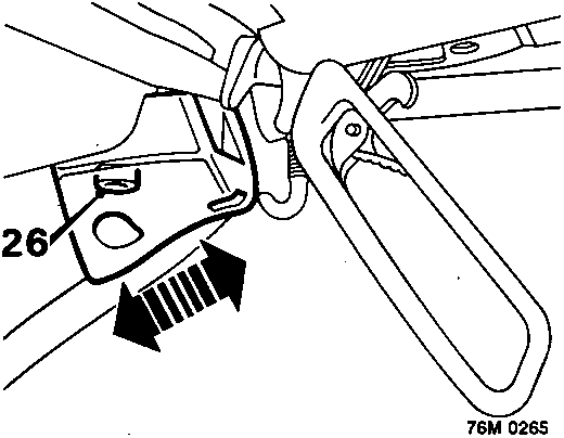
- Slacken header securing bolts and adjust position of header in its slotted mountings.
- Tighten header securing bolts and raise hood.
- Engage hooks in ‘A’ post locations, but leave handles in ‘unlocked’ position.
- Check for correct gap between header locating pins and plastic striker plates. Adjust if necessary, ensuring that hood is fully lowered before header mounting bolts are slackened.
Hood frame – Adjust
- With hood in lowered position; fit hood hinge covers and secure with fixing stud and screw.
- Check and Adjust – Cantrail Tensioning.
Parts & tools for this job For Rover Coupé, Cabriolet & Tourer
- TOOLTrim removal tool kitSearch: trim removal tool kit
- PARTTouch-up paintSearch: Rover touch up paint
- PARTPanel clip assortmentSearch: Rover panel clips assortment
Links open Amazon search results in a new tab. As an Amazon Associate I earn from qualifying purchases.