
Refit
- Make
- Rover
- Model
- Coupé, Cabriolet & Tourer 200/400 Coupé, Cabriolet & Tourer Workshop Manual
- Section
- Hood › Refit
BodyRefit
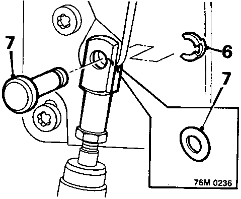
- Remove retaining clip from hood ram trunnion clevis pin.
- Remove clevis pin and collect Belville washer from trunnion.
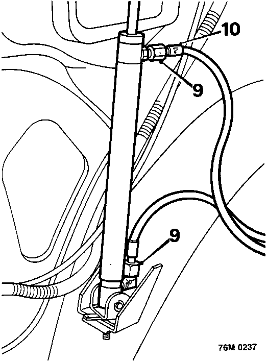
- Position a drip tray beneath ram to collect any fluid spillage.
- Slacken hose unions at ram.
- Mark relationship of hoses to ram.
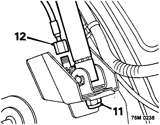
- Remove Nyloc nut from base of ram, place ram in drip tray and collect headlining strap locating plate from ram mounting bracket.
- Disconnect hoses from ram and plug ends of hoses and ram unions.
Refit
- Position new ram in drip tray, remove plugs from ram unions and hoses, then loosely fit hose unions to ram.
- Position headlining strap locating plate on ram mounting plate.
Note: When correctly fitted, locating plate will point forwards.
- Position ram on mounting bracket, fit and tighten Nyloc nut and tighten hose unions.
Rams – adjust – both sides
- Position a 50 mm deep wooden support block on header rail.
- Manually raise hood onto support block.
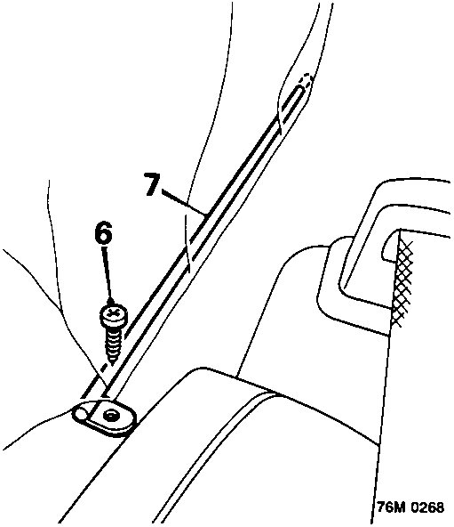
- Remove screw securing headlining tension rod on opposite side to renewed ram.
- Remove tension rod from headlining.
Parts & tools for this job For Rover Coupé, Cabriolet & Tourer
- TOOLTrim removal tool kitSearch: trim removal tool kit
- PARTTouch-up paintSearch: Rover touch up paint
- PARTPanel clip assortmentSearch: Rover panel clips assortment
Links open Amazon search results in a new tab. As an Amazon Associate I earn from qualifying purchases.