
Air conditioning (Refrigerant system): Description and operation
- Make
- Land Rover
- Model
- Discovery II (UK)
- Section
- Description and operation › Refrigerant system
Refrigerant system
Schematic of air conditioning system
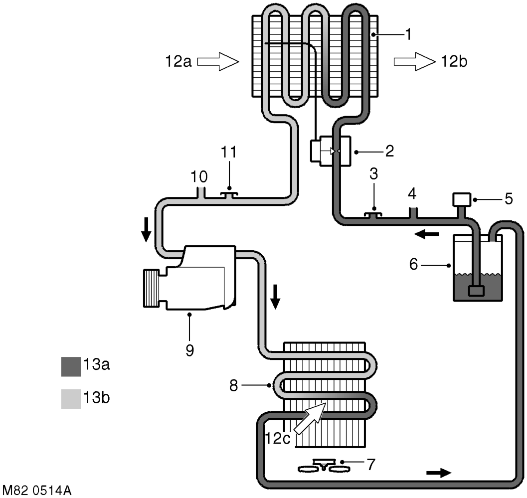
1 Evaporator 2 Thermostatic expansion valve 3 Low pressure servicing connection 4 Outlet to rear A/C system (where fitted) 5 Dual pressure switch 6 Receiver drier 7 Cooling fan 8 Condenser 9 Compressor
10 Inlet from rear A/C system (where fitted) 11 High pressure servicing connection 12 Air flows a Ambient air b Cooled air c Ambient air through condenser 13 Refrigerant a Liquid b Vapour
The refrigerant system transfers heat from the vehicle interior to the outside atmosphere to provide the heater assembly with dehumidified cool air. The system comprises a compressor, condenser, receiver drier, thermostatic expansion valve and evaporator, joined together by refrigerant lines. The system is a sealed, closed loop, filled with a charge weight of R134a refrigerant as the heat transfer medium. Oil is added to the refrigerant to lubricate the internal components of the compressor.
Parts & tools for this job For Land Rover Discovery
- TOOLA/C manifold gauge setSearch: AC manifold gauge set
- TOOLUV leak detection kitSearch: AC UV leak detection kit
- PARTCabin filterSearch: Land Rover Discovery cabin filter
Links open Amazon search results in a new tab. As an Amazon Associate I earn from qualifying purchases.