
Air conditioning (Refrigerant system): Description and operation (page 2 of 4)
- Make
- Land Rover
- Model
- Discovery II (UK)
- Section
- Description and operation
To accomplish the transfer of heat, the refrigerant is circulated around the system, where it passes through two pressure/temperature regimes. In each of the pressure/temperature regimes, the refrigerant changes state, during which process maximum heat absorption or release occurs. The low pressure/temperature regime is from the thermostatic expansion valve, through the evaporator to the compressor; the refrigerant decreases in pressure and temperature at the thermostatic expansion valve, then changes state from liquid to vapour in the evaporator, to absorb heat. The high pressure/temperature regime is from the compressor, through the condenser and receiver drier to the thermostatic expansion valve; the refrigerant increases in pressure and temperature as it passes through the compressor, then releases heat and changes state from vapour to liquid in the condenser.
Compressor
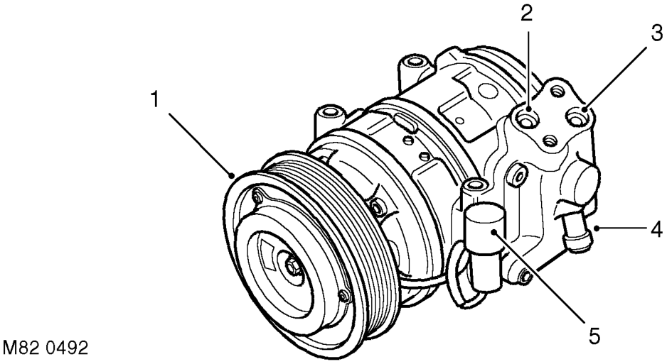
1 Pulley 2 Inlet connection 3 Outlet connection 4 Pressure relief valve 5 Clutch connector
The compressor circulates the refrigerant around the system by compressing low pressure, low temperature vapour from the evaporator and discharging the resultant high pressure, high temperature vapour to the condenser.
The compressor is attached to a mounting bracket on the engine, and is a ten cylinder swash plate unit with a fixed displacement of 177 ml/rev (0.19 US qt/rev). The auxiliary drive belt drives the compressor via a pulley and an electrically actuated clutch. Operation of the clutch is controlled by the Engine Control Module (ECM).
To protect the refrigerant system from unacceptably high pressure, a pressure relief valve is installed in the outlet side 2
of the compressor. The pressure relief valve is set to operate at 34.3 to 41.4 bars (497 to 600 lbf.in ) and vents excess pressure into the engine compartment.
Parts & tools for this job For Land Rover Discovery
- TOOLA/C manifold gauge setSearch: AC manifold gauge set
- TOOLUV leak detection kitSearch: AC UV leak detection kit
- PARTCabin filterSearch: Land Rover Discovery cabin filter
Links open Amazon search results in a new tab. As an Amazon Associate I earn from qualifying purchases.