
Inlet manifold stub pipes - ’k’ series
- Make
- Rover
- Model
- 400 Workshop Manual
- Year
- 1995–2000
- Section
- Repairs › Inlet manifold stub pipes - ’k’ series
‹ Prev Inlet manifold chamber gasket - ’t’ seriesNext › Inlet manifold gasket - ’d’ series 97.5 my on
Manifold & exhaust systemsInlet manifold stub pipes - ’k’ series
INLET MANIFOLD STUB PIPES - ’K’ SERIES
Service repair no - 30.15.42
Should a plastic manifold stub pipe break, it can be replaced using the following procedure.
Renew
- Remove inlet manifold assembly. See this section.
- Position manifold on work bench, clamp manifold flange and support manifold chamber.
- If pipe has broken off above boss face, file stub level with bose face.
- Measure diameter of stub pipe which has broken.
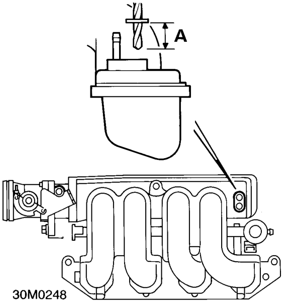
5mm stub pipe (Part No. UKC 2487)
- Use a clean 5mm drill, with a fibre washer set 13mm from tip ’A’.
6mm stub pipe (Part No. UKC 2487)
- Use a clean 6mm drill, with a fibre washer set 13mm from tip ’A’.
Both stub pipes
- Carefully drill hole to depth.
WARNING: Safety goggles must be worn when drilling.
- Lightly chamfer edge of drilled hole.
- Select replacement stub pipe, spray stub and drilled hole with Loctite activator N.
NOTE: Allow activator to fully dry and do not contaminate surfaces.
- Lightly smear drilled hole and stub pipe with Loctite 648.
- Fit stub pipe into plastic manifold.
NOTE: Leave manifold for one hour to allow Loctite to partially cure.
- Un-clamp manifold from work bench and using an air line, blow out and excess Loctite from stub pipe and swarf from manifold.
- Fit inlet manifold assembly. See this section.
NOTE: When connecting hose to repaired stub pipe, avoid twisting or excessive bending.
NOTE: The vehicle is fit for service, but full strength of joint will be achieved after approximately 10 hours.
‹ Prev Inlet manifold chamber gasket - ’t’ seriesNext › Inlet manifold gasket - ’d’ series 97.5 my on
Parts & tools for this job For 1995 Rover 400
- PARTExhaust gasketSearch: Rover 400 1995 exhaust gasket
- TOOLPenetrating oilSearch: penetrating oil
- TOOLOBD2 scannerSearch: OBD2 scanner
Links open Amazon search results in a new tab. As an Amazon Associate I earn from qualifying purchases.