
Compensator arm (page 2 of 2)
- Make
- Rover
- Model
- 400 Workshop Manual
- Year
- 1995–2000
- Section
- Repairs
SuspensionCompensator arm · page 2 of 2
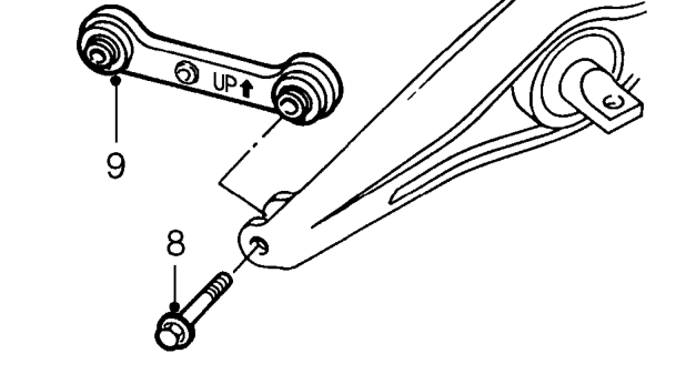
- Pull forward end of trailing arm downwards.
- Remove bolt securing compensator arm to trailing arm.
- Remove compensator arm.
Refit
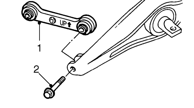
- Position compensator arm to trailing arm with ’UP’ mark and arrow positioned as illustrated and facing the front of the vehicle.
NOTE: Arms are interchangeable LH to RH side of vehicle.
- Fit bolt, but DO NOT tighten.
- Align trailing arm to body, fit bolts and tighten to 78 Nm.
- Lever trailing arm inwards and connect compensator arm to body bracket. Fit bolt and flat washer, but DO NOT tighten.
- Tighten bolt securing compensator arm to trailing arm to 45 Nm.
- Lever trailing arm inwards, align centre of bolt with reference mark and tighten to 45 Nm.
- Fit road wheel(s) and tighten nuts to correct torque. See INFORMATION, Torque wrench settings.
- Remove stand(s) and lower vehicle.
- Check rear wheel alignment. See STEERING, Adjustments.
Parts & tools for this job For 1995 Rover 400
- TOOLCoil spring compressorSearch: coil spring compressor
- TOOLBall joint separatorSearch: ball joint separator
- PARTShock absorbersSearch: Rover 400 1995 shock absorbers
Links open Amazon search results in a new tab. As an Amazon Associate I earn from qualifying purchases.