
Drive and Driven Gears Removal (page 3 of 3)
- Make
- Rover
- Model
- 600 Rover 600 Repair Manual - Volumes 1 and 2 - 2nd Edition
- Section
- Repairs
SteeringDrive and Driven Gears Removal · page 3 of 3
CAUTION: Pump components are made of aluminium. Be careful not to damage them when servicing.
- Clean all of the disassembled parts thoroughly.
- Replace all O-rings and seals. Do not dip new O-rings and seals in solvent; coat O-rings with steering grease before installation, and make sure they stay in place during reassembly.
- The shaded parts are selectively fitted, and should not be disassembled except to replace seals. If any one of them is faulty, replace the whole pump as an assembly.
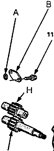
- A O-ring
- B Housing Port Cover B
- C Housing Seal
- D Port Housing
- E 6 mm Flange Bolt
- F Dowel Pins
- G Pump Housing
- H Driven Gear
- I Housing Port Cover
- J Dowel Pins
- K Drive Gear
- L Plunger B
- M Plunger Seal
- N Flow Control Valve
- O Oil Seal
- P Plunger A
- Q Flange Bolt
- R Housing Seal
- S Pulley Key
- T Pump Front Cover
- U Pulley
- V Flange Bolt
- W Pulley Nut
- X Valve Spring
Parts & tools for this job For Rover 600
- TOOLTie rod end toolSearch: tie rod end puller
- TOOLBall joint separatorSearch: ball joint separator
- FLUIDPower steering fluidSearch: Rover power steering fluid
Links open Amazon search results in a new tab. As an Amazon Associate I earn from qualifying purchases.