
Power Steering Pump Preload Inspection (page 2 of 3)
- Make
- Rover
- Model
- 600 Rover 600 Repair Manual - Volumes 1 and 2 - 2nd Edition
- Section
- Repairs
SteeringPower Steering Pump Preload Inspection · page 2 of 3
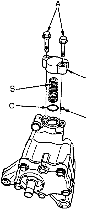
B Valve Spring
C 17.8 x 1.9 mm O-ring
D Housing Port Cover
- Remove the two 6 mm flange bolts, then remove the housing port cover, valve spring and O-rings. Replace O-rings.
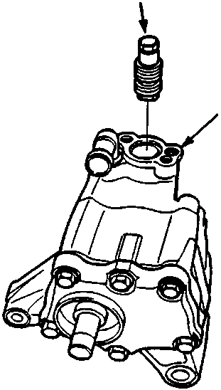
B Port Housing
- Remove the flow control valve from the port housing.
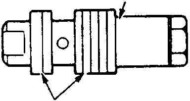
B Check for damage
- Check for wear, burrs, and other damage to the edges of the grooves in the flow control valve.
Parts & tools for this job For Rover 600
- TOOLTie rod end toolSearch: tie rod end puller
- TOOLBall joint separatorSearch: ball joint separator
- FLUIDPower steering fluidSearch: Rover power steering fluid
Links open Amazon search results in a new tab. As an Amazon Associate I earn from qualifying purchases.