
Power Steering Pump Preload Inspection (page 3 of 3)
- Make
- Rover
- Model
- 600 Rover 600 Repair Manual - Volumes 1 and 2 - 2nd Edition
- Section
- Repairs
SteeringPower Steering Pump Preload Inspection · page 3 of 3
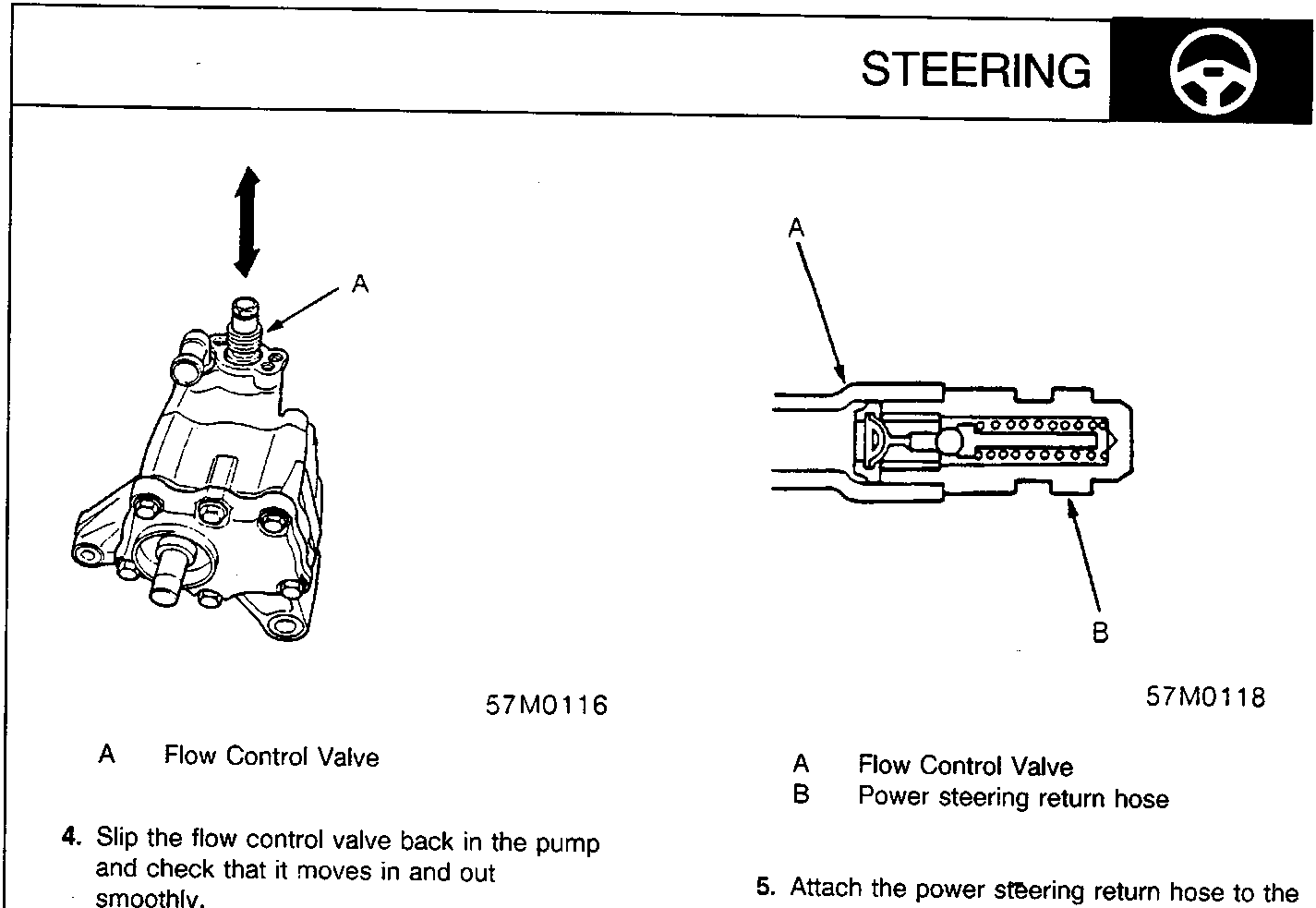
A Flow Control Valve
- Slip the flow control valve back in the pump and check that it moves in and out smoothly.
If OK, go on to next step; if not, replace the flow control valve.
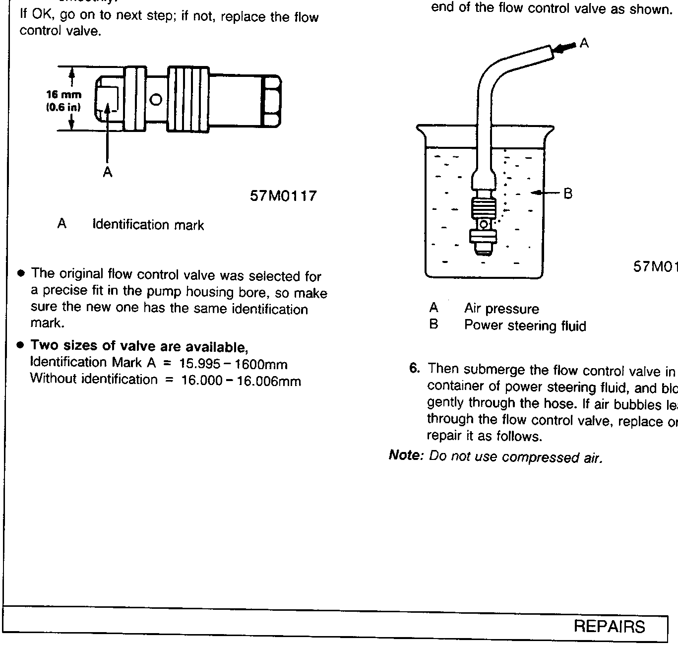
A Identification mark
- The original flow control valve was selected for a precise fit in the pump housing bore, so make sure the new one has the same identification mark.
- Two sizes of valve are available,
Identification Mark A = 15.995 – 16.000mm
Without identification = 16.000 – 16.006mm
A Flow Control Valve
B Power steering return hose
- Attach the power steering return hose to the end of the flow control valve as shown.
A Air pressure
B Power steering fluid
- Then submerge the flow control valve in a container of power steering fluid, and blow gently through the hose. If air bubbles leak through the flow control valve, replace or repair it as follows.
Note: Do not use compressed air.
Parts & tools for this job For Rover 600
- TOOLTie rod end toolSearch: tie rod end puller
- TOOLBall joint separatorSearch: ball joint separator
- FLUIDPower steering fluidSearch: Rover power steering fluid
Links open Amazon search results in a new tab. As an Amazon Associate I earn from qualifying purchases.