
Steering gearbox (page 2 of 3)
- Make
- Rover
- Model
- 600 Rover 600 Repair Manual - Volumes 1 and 2 - 2nd Edition
- Section
- Repairs
SteeringSteering gearbox · page 2 of 3
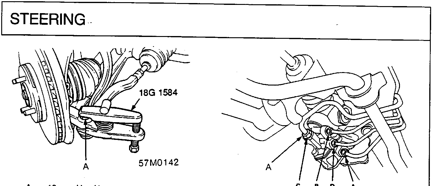
A 10 mm Hex Nut
57M0142
57M0144
- Remove the cotter pin from the castle nut and remove the nut.
- Install the 10 mm hex nut on the ball joint. Be sure that the 10 mm hex nut is flush with the ball joint pin end, or the threaded section of the ball joint pin might be damaged by the ball joint remover.
- Separate the tie - rod ball joint and knuckle using the special tool.
CAUTION: Avoid damaging the ball joint boot.
- Remove the gearbox shield.
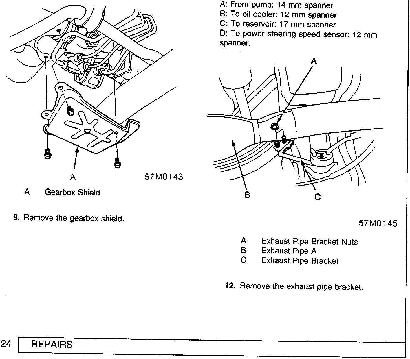
A Gearbox Shield
57M0143
A Valve Body Unit
- Using solvent and a brush, wash any oil and dirt off the valve body unit, its lines, and that end of the gearbox, and blow them dry with compressed air.
- Using flare nut spanners, disconnect the four lines from the valve body unit.
A: From pump: 14 mm spanner
B: To oil cooler: 12 mm spanner
C: To reservoir: 17 mm spanner
D: To power steering speed sensor: 12 mm spanner.
A Exhaust Pipe Bracket Nuts
B Exhaust Pipe A
C Exhaust Pipe Bracket
57M0145
- Remove the exhaust pipe bracket.
Parts & tools for this job For Rover 600
- TOOLTie rod end toolSearch: tie rod end puller
- TOOLBall joint separatorSearch: ball joint separator
- FLUIDPower steering fluidSearch: Rover power steering fluid
Links open Amazon search results in a new tab. As an Amazon Associate I earn from qualifying purchases.