
Steering gearbox (page 3 of 3)
- Make
- Rover
- Model
- 600 Rover 600 Repair Manual - Volumes 1 and 2 - 2nd Edition
- Section
- Repairs
SteeringSteering gearbox · page 3 of 3
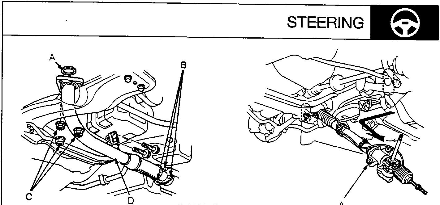
A Gasket
B Self – locking Nut
C Self – locking Nut
D Exhaust Pipe A
A Gearbox Assembly
- Remove the self – locking nuts that connect the exhaust pipe A to the three way catalytic converter, and the exhaust pipe A to the exhaust manifold.
- Remove the exhaust pipe A.
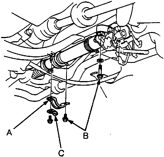
A Holder
B Steering Gearbox Mounting Bolts
C Air Transfer Hose Clamp
- Remove the steering gearbox mounting bolts, holder and air transfer hose clamp.
- Remove the left tie – rod end, then slide the tie rod all the way to the right side.
- Slide the gearbox right so that the left tie rod clears the bottom of the rear beam, then remove the gearbox assembly.
CAUTION: Be careful not to bend or damage the four power steering lines when removing the gearbox assembly.
Parts & tools for this job For Rover 600
- TOOLTie rod end toolSearch: tie rod end puller
- TOOLBall joint separatorSearch: ball joint separator
- FLUIDPower steering fluidSearch: Rover power steering fluid
Links open Amazon search results in a new tab. As an Amazon Associate I earn from qualifying purchases.