
No 2. injector only (page 3 of 5)
- Make
- Rover
- Model
- 600 620 Diesel Repair Manual Supplement
- Year
- 1995–1999
- Section
- Repairs
Engine management systemNo 2. injector only · page 3 of 5
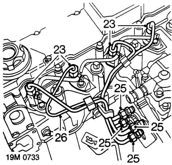
- Slacken injector pipe unions at injectors.
- Position absorbent cloth around fuel injection pump pipe connections to catch fuel spillage.
- Slacken injector pipe unions from fuel injection pump.
CAUTION: To prevent damage to fuel injection pipes or components use 2 spanners when loosening unions.
- Disconnect injector pipe unions from fuel injection pump and injectors, remove injector pipe assembly.
CAUTION: Plug the connections.
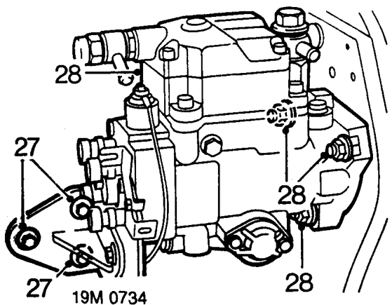
- Remove 3 bolts securing injection pump support bracket to engine.
- Remove 3 nuts securing injection pump to gearbox mounting plate, remove injection pump.
Parts & tools for this job For 1995 Rover 600
- PARTFuel filterSearch: Rover 600 1995 fuel filter
- TOOLFuel pressure test kitSearch: fuel pressure test kit
- TOOLFuel line disconnect toolSearch: fuel line disconnect tool
Links open Amazon search results in a new tab. As an Amazon Associate I earn from qualifying purchases.