
Gearbox assembly (page 4 of 9)
- Make
- Rover
- Model
- 800 Workshop Manual
- Year
- 1996–1999
- Section
- Repairs
Manual gearbox - PG1Gearbox assembly · page 4 of 9
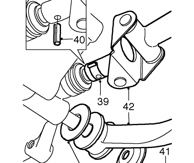
- Remove selector rod roll pin cover.
- Remove selector rod roll pin.
- Remove selector steady rod bolt.
- Release steady rod and selector rod from gearbox.
- Collect 2 steady rod washers.
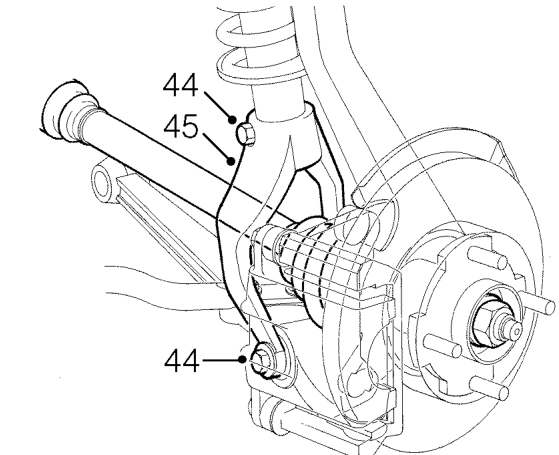
- Remove 2 bolts securing LH suspension yoke to lower arm and damper.
- Remove yoke.
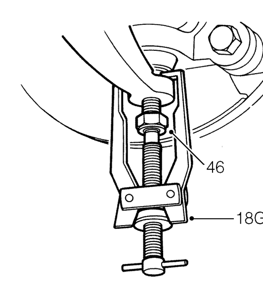
- Remove nuts from LH and RH lower ball joints.
- Break taper joints using tool 18G 2 and release knuckles from lower arms.
CAUTION: Do not damage ball joint boot.
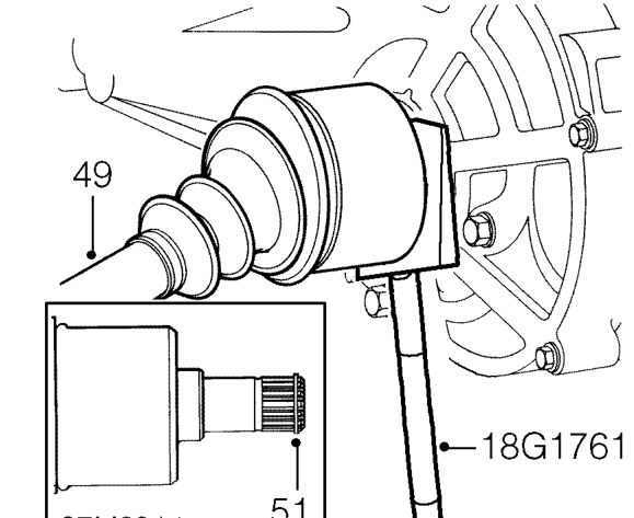
- Release drive shafts from differential using tool 18G 1761.
- Turn steering on LH lock and disconnect LH drive shaft from differential.
- Turn steering on RH lock and disconnect RH drive shaft from differential.
CAUTION: Keep drive shafts horizontal to avoid damaging differential oil seals.
- Remove and discard circlip from end of each drive shaft.
Parts & tools for this job For 1996 Rover 800
- PARTClutch kitSearch: Rover 800 1996 clutch kit
- TOOLClutch alignment toolSearch: clutch alignment tool
- FLUIDGear oilSearch: Rover 800 manual gearbox oil
Links open Amazon search results in a new tab. As an Amazon Associate I earn from qualifying purchases.