
Remove (page 2 of 2)
- Make
- Rover
- Model
- Coupé, Cabriolet & Tourer 200/400 Coupé, Cabriolet & Tourer Workshop Manual
- Section
- Hood
BodyRemove · page 2 of 2
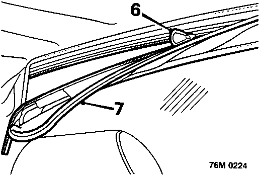
- Peel Velcro away from top of backlight to reveal zip.
- Unfasten backlight zip and lay backlight in rear shelf.
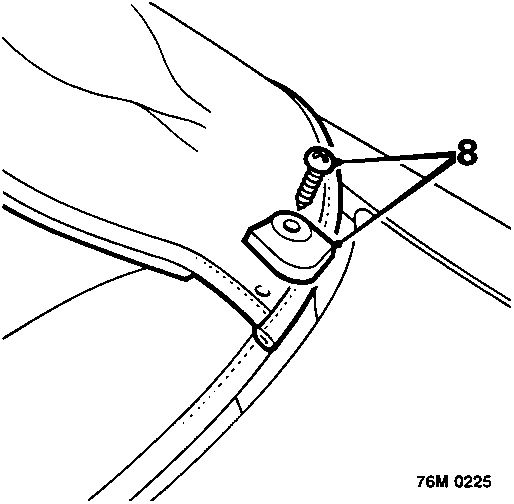
- Remove screws securing rear corners of hood to backlight and remove corner finishers.
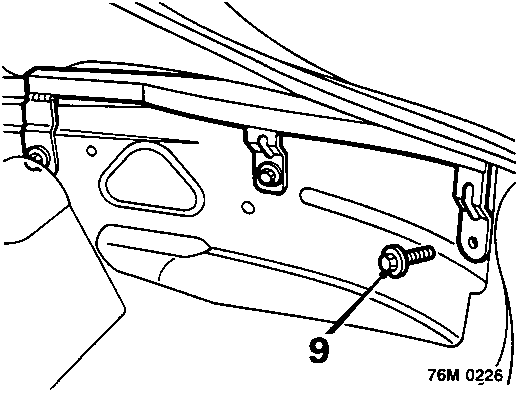
- Remove screws securing hood rear quarters to inside of body.
- Lower both rear windows.
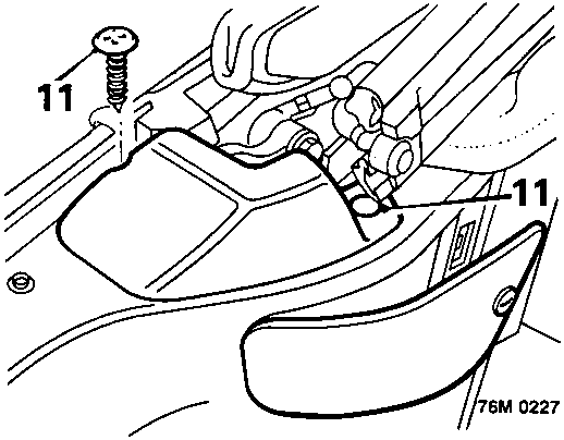
- Remove screw and trim stud from each hood hinge cover and remove hinge covers.
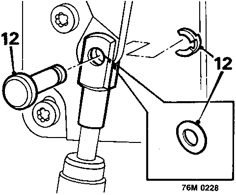
- Remove retaining clip, retain and Belville washer as clevis pin is withdrawn from strut trunnion.
- With assistance, carefully lower hood whilst guiding the loose hood struts through hood frame.
WARNING: Ensure that hands are not trapped in hood frame as it is lowered.
CAUTION: Ensure that struts are held in a 'safe' position whilst hood is lowered to avoid damage to hood or headlining.
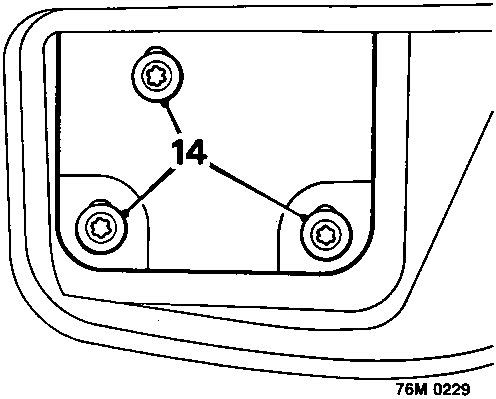
- Remove Torx screws (TX40 Torx bit) from hood hinges.
- Place protective cover on luggage compartment lid to prevent damage as hood assembly is removed.
- With assistance, establish lifting points on each side of hood frame.
CAUTION: Lifting points should be as far
Parts & tools for this job For Rover Coupé, Cabriolet & Tourer
- TOOLTrim removal tool kitSearch: trim removal tool kit
- PARTTouch-up paintSearch: Rover touch up paint
- PARTPanel clip assortmentSearch: Rover panel clips assortment
Links open Amazon search results in a new tab. As an Amazon Associate I earn from qualifying purchases.