
Bearings - connecting rods
- Make
- Land Rover
- Model
- Discovery II (UK)
- Section
- Overhaul › Bearings - connecting rods
Engine - V8Bearings - connecting rods
Bearings - connecting rods
$% 12.17.16.01
Disassembly
- Remove oil pick up strainer. ENGINE - V8, OVERHAUL, Strainer - oil pick-up.
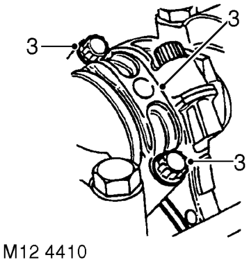
- Suitably mark cylinder reference number on each connecting rod bearing cap.
- Remove 2 bolts securing each connecting rod bearing cap, remove caps and recover connecting rod bearings.
CAUTION: Keep bearing caps, bearings and bolts in their fitted order.
- Push each connecting rod up cylinder bore until connecting rods are clear of crankshaft journals.
CAUTION: Ensure that connecting rods do not contact cylinder bores.
- Remove bearing shells from each connecting rod.
Inspect
- Clean crankshaft journals and bearing locations in connecting rods.
- Inspect connecting rod bearings for wear and renew if necessary. Connecting rod bearings are available in two oversizes. l Connecting rod bearing 1st oversize = 0.254 mm (0.01 in). l Connecting rod bearing 2nd oversize = 0.508 mm (0.02 in).
- Check crankshaft big-end journals for wear and scoring. Measure for ovality; taking 3 measurements at 120° intervals at each end and at centre of journals. l Standard journal = 55.500 to 55.513 mm (2.20 to 2.22 in). l 1st undersize journal - 0.254 mm (0.01 in) = 55.246 to 55.259 mm (2.17 to 2.18 in). l 2nd undersize journal - 0.508 mm (0.02 in) = 54.992 to 55.005 mm (2.16 to 2.165 in). l Journal - max. ovality = 0.040 mm (0.002 in)
Reassembly
- Clean connecting rod caps.
- Lubricate connecting rod journals and bearing shells with clean engine oil.
- Fit bearing shells to connecting rods and caps.
- Rotate crankshaft until connecting rod journals are correctly positioned.
- Taking care not to displace bearing shells, pull connecting rods on to crankshaft journals.
- Check that bearing shells are correctly located in connecting rod bearing caps.
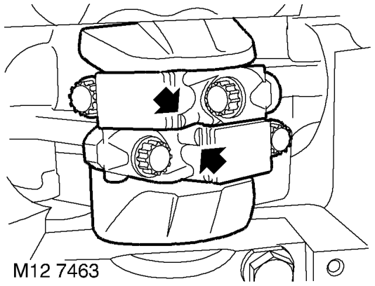
- Fit connecting rod bearing caps, ensuring that they are in their correct fitted order. NOTE: The rib on the edge of the bearing cap must face towards the front of engine on the RH bank of cylinders and towards the rear on the LH bank.
- Lightly oil threads of connecting rod bolts. Fit connecting rod bolts and tighten to 20 Nm (15 lbf.ft) then turn a further 80°.
Parts & tools for this job For Land Rover Discovery
- PARTEngine gasket setSearch: Land Rover Discovery engine gasket set
- TOOLTorque wrenchSearch: 3/8 inch torque wrench
- TOOLFeeler gauge setSearch: feeler gauge set
Links open Amazon search results in a new tab. As an Amazon Associate I earn from qualifying purchases.