
Piston assemblies
- Make
- Land Rover
- Model
- Discovery II (UK)
- Section
- Overhaul › Piston assemblies
Engine - V8Piston assemblies · page 1 of 3
Piston assemblies
$% 12.17.02.01
Disassembly
- Remove cylinder head. ENGINE - V8, OVERHAUL, Gasket - cylinder head.
- Remove oil pick-up strainer ENGINE - V8, OVERHAUL, Strainer - oil pick-up.
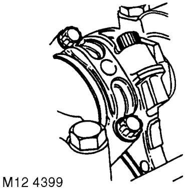
- Suitably identify each connecting rod and piston assembly to its respective cylinder bore.
- Remove 2 bolts securing each connecting rod bearing cap.
- Remove connecting rod bearing cap and collect connecting rod bearings.
- Remove ridge of carbon from top of cylinder bores.
- Carefully push each piston assembly from the top of the cylinder.
CAUTION: Ensure that connecting rods do not contact cylinder bores.
- Refit bearing cap onto connecting rod, lightly tighten dowel bolts.
- Suitably identify each piston to its respective connecting rod.
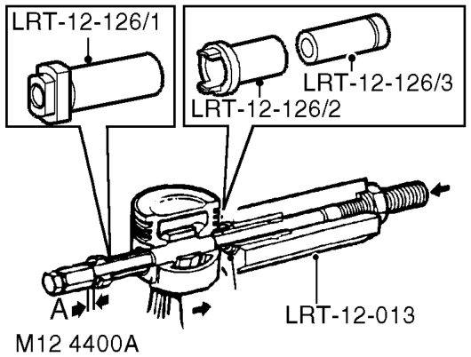
- Position body of tool LRT-12-013 in vice.
- Screw large nut back until flush with end of centre screw.
- Push centre screw forward until nut contacts thrust race.
- Fit piston adapter tool LRT-12-126/2 .
- Position guide pin tool LRT-12-126/3 in LRT- 12-126/2 with groove facing away from piston.
- Locate piston and connecting rod assembly on centre screw and up to adapter tool LRT-12- 126/2.
- Fit remover/replacer bush tool LRT-12-126/1 on centre screw with flanged end facing away from gudgeon pin.
- Screw stop nut onto centre screw leaving clearance of 3 mm (0.125 in), dimension 'A', between nut and remover/replacer bush.
- Lock the stop nut securely with lock screw.
- Push connecting rod to locate end of gudgeon pin in adapter tool LRT-12-126/2.
- Ensure remover/replacer is located in gudgeon pin bore of piston.
- Screw large nut up to tool LRT-12-013.
- Hold lock nut and turn large nut until gudgeon pin is withdrawn from piston.
- Dismantle tool and remove piston, connecting rod and gudgeon pin.
Parts & tools for this job For Land Rover Discovery
- PARTEngine gasket setSearch: Land Rover Discovery engine gasket set
- TOOLTorque wrenchSearch: 3/8 inch torque wrench
- TOOLFeeler gauge setSearch: feeler gauge set
Links open Amazon search results in a new tab. As an Amazon Associate I earn from qualifying purchases.