
- oil pick-up.
- Make
- Land Rover
- Model
- Discovery II (UK)
- Section
- Overhaul › - oil pick-up.
Engine - V8- oil pick-up.
- Fit 2nd compression ring marked 'TOP' with marking uppermost in 2nd groove.
- Fit 1st compression ring in first groove either way round.
- Check piston ring to groove clearance. l 1st compression ring = 0.05 to 0.10 mm (0.002 to 0.004 in). l 2nd compression ring = 0.05 to 0.10 mm (0.002 to 0.004 in).
- Position oil control expander ring joint and ring rail gaps all at one side, between gudgeon pin and away from LH side of piston - viewed from front of piston. Position the gaps in ring rails approximately 25 mm (1.0 in) each side of expander ring joint.
- Position compression rings with gaps on
- Insert connecting rod and piston into its
opposite side of piston between gudgeon pin and RH side of piston - viewed from front of piston.
- Thoroughly clean cylinder bores.
- Lubricate piston rings and gudgeon pin with
- Clean connecting rod journal and bearing cap.
clean engine oil.
- Lubricate connecting rod journal and
- Lubricate cylinder bore with clean engine oil.
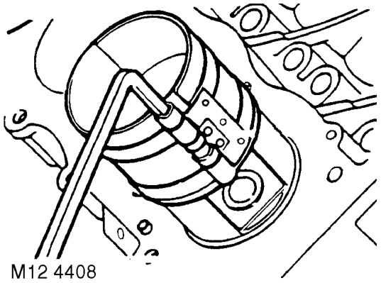
- Fit connecting rod bearings and connecting rod
- Using LRT-12-204, compress piston rings.
- Fit bolts and tighten to 20 Nm (15 lbf.ft) then
- Fit oil pick-up strainer.
- Fit cylinder head gasket.
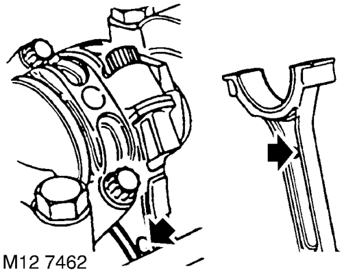
respective cylinder bore, ensuring domed shaped boss on connecting rod faces towards front of engine on RH bank of cylinders and towards rear on LH bank of cylinders.
connecting rod bearings.
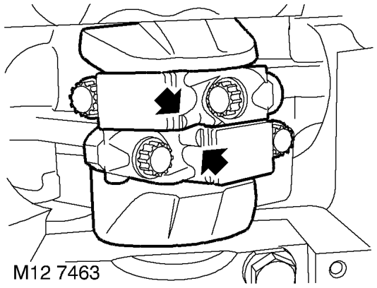
bearing caps ensuring they are in their correct fitted order. NOTE: The rib on the edge of the bearing cap must face towards the front of the engine on the RH bank of cylinders and towards the rear on the LH bank.
turn a further 80°.
ENGINE - V8, OVERHAUL, Strainer
- oil pick-up.
ENGINE - V8, OVERHAUL, Gasket -
cylinder head.
Parts & tools for this job For Land Rover Discovery
- PARTOil filterSearch: Land Rover Discovery oil filter
- TOOLOil filter wrenchSearch: oil filter wrench
- FLUIDEngine oilSearch: Land Rover Discovery engine oil
Links open Amazon search results in a new tab. As an Amazon Associate I earn from qualifying purchases.