
Engine and gearbox with air conditioning (page 12 of 12)
- Make
- Rover
- Model
- 400 Workshop Manual
- Year
- 1995–2000
- Section
- Repairs
Engine - K SeriesEngine and gearbox with air conditioning · page 12 of 12
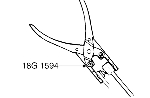
- Clean gear selector linkage and gear change linkage ball joints.
- Position gear selector linkage through rear engine mounting bracket and using tool 18G 1594 connect ball joints to gear selector and gear selector lever.
- Using tool 18G 1594 connect gear change linkage ball joint to gear change lever.
- Connect 3 engine harness multiplugs to main harness.
- Secure multiplugs to mounting bracket.
- Secure engine harness to mounting brackets.
- Connect positive lead to engine compartment fusebox and secure with screw.
- Fit engine compartment fusebox cover.
- Secure air conditioning relay module to mounting bracket.
- Fit evaporative emission canister to mounting bracket.
- Secure evaporative emission canister breather hose to clips on fuel pipe.
- Connect hose to fuel tank vent pipe.
- Connect purge hose to throttle housing and secure with clip.
- Connect multiplug to evaporative emission canister purge valve.
- Secure fuel trap to engine control module mounting bracket.
- Position relay module and connect 2 multiplugs.
- Fit relay module to mounting bracket.
- Fit 2 bolts securing mounting bracket to body and tighten to 9 Nm.
- Secure engine harness clip to mounting bracket.
- Fit engine control module. See ENGINE MANAGEMENT SYSTEM - MEMS, Repairs.
- Clean 2 ends of clutch hydraulic pipe.
- Connect 2 halves of clutch hydraulic pipe, ensure 2 halves are correctly engaged by trying to pull hydraulic pipes away from connector.
- Secure clutch hydraulic pipe to clip on harness.
- Connect 2 earth leads to starter motor upper bolt.
- Fit upper bolt securing starter motor to engine and tighten to 45 Nm.
- Connect battery cable to starter solenoid and secure with nut.
- Fit plastic cap to nut securing battery cable to starter solenoid.
- Remove caps from air conditioning pipes and compressor.
- Clean mating face of compressor and air conditioning pipe union.
- Lubricate 2 new ’O’ rings with refrigerant oil and fit to compressor.
- Position air conditioning pipe union to compressor, fit bolt and tighten to 45 Nm.
- Clean condenser pipe and compressor pipe unions.
- Lubricate new ’O’ ring with refrigerant oil and fit to condenser pipe.
- Connect condenser pipe to compressor pipe and tighten union to 25 Nm.
CAUTION: To prevent damage to air conditioning pipes or components use two backing spanners when loosening or tightening unions.
- Clean compressor pipe and evaporator unions.
- Lubricate new ’O’ ring with refrigerant oil and fit to evaporator pipe.
- Connect compressor pipe to evaporator pipe and tighten union to 45 Nm.
- Align air conditioning pipe to bracket on flywheel housing, fit bolt and tighten to 9 Nm.
- Replace receiver drier. See AIR CONDITIONING, Adjustments.
Parts & tools for this job For 1995 Rover 400
- PARTEngine gasket setSearch: Rover 400 1995 engine gasket set
- TOOLTorque wrenchSearch: 3/8 inch torque wrench
- TOOLFeeler gauge setSearch: feeler gauge set
Links open Amazon search results in a new tab. As an Amazon Associate I earn from qualifying purchases.