
86M 1952
- Make
- Rover
- Model
- 600 Rover 600 Repair Manual - Volumes 1 and 2 - 2nd Edition
- Section
- Wire harness and earth locations › 86M 1952
Electrical86M 1952
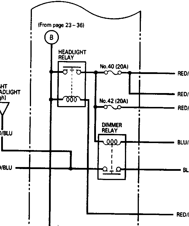
UNDER-HOOD FUSE/RELAY BOX
(From page 23-36)
- LEFT HEADLIGHT (High)
- HIGH BEAM INDICATOR
- RIGHT HEADLIGHT (High)
| Component | Fuse | Wire Color | Destination |
|---|---|---|---|
| HEADLIGHT RELAY | No.40 (20A) | RED/GRN | Right headlight (Low) Right headlight (High) |
| RED/GRN | High beam indicator | ||
| No.42 (20A) | RED/YEL | Left headlight (Low) Left headlight (High) |
|
| DIMMER RELAY | BLU/RED | COMBINATION LIGHT SWITCH (To page 23-38,39) |
|
| BLK | G203 | ||
| RED/BLU | COMBINATION LIGHT SWITCH (To page 23-38,39) |
||
| No.19 (30A) | RED/GRN | COMBINATION LIGHT SWITCH (To page 23-38,39) |
|
| No.27 (10A) | BLU/RED | COMBINATION LIGHT SWITCH (To page 23-38,39) |
B
RED/BLU
RED/BLU
86M 1952
Parts & tools for this job For Rover 600
- TOOLDigital multimeterSearch: automotive digital multimeter
- PARTAssorted fuse kitSearch: car fuse assortment kit
- TOOLWire crimper and connector kitSearch: wire crimper connector kit
Links open Amazon search results in a new tab. As an Amazon Associate I earn from qualifying purchases.