
Under-dash fuse/relay box
- Make
- Rover
- Model
- 600 Rover 600 Repair Manual - Volumes 1 and 2 - 2nd Edition
- Section
- Wire harness and earth locations › Under-dash fuse/relay box
ElectricalUnder-dash fuse/relay box
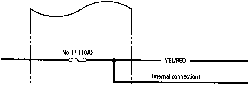
IGNITION SWITCH (ACC) (From page 23-40)
IGNITION SWITCH (ST) (From page 23-40)
UNDER-DASH FUSE/RELAY BOX
No.11 (10A)
YEL/RED — Stereo radio/cassette player (Option A)
(Internal connection)
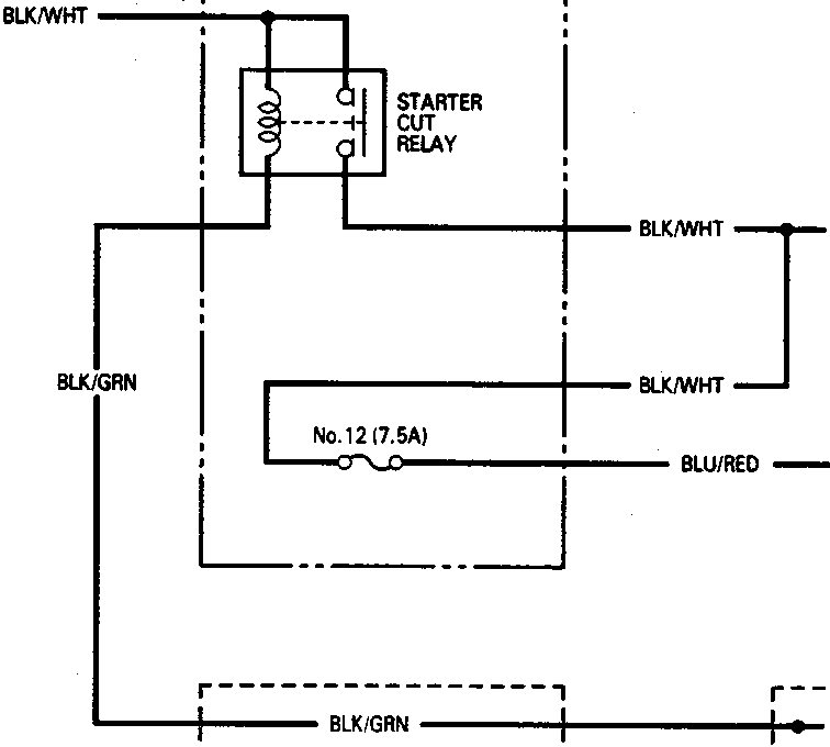
STARTER CUT RELAY
No.12 (7.5A)
BLK/WHT — Starter solenoid
BLU/RED — Engine control module (ECM) PGM–FI main relay
BLK/GRN — Security alarm control unit (With security alarm system)
NEUTRAL POSITION SWITCH (In A/T gear position switch)
BLK/GRN — G501 (Without security alarm system)
86M 1957
WIRE HARNESS AND EARTH LOCATIONS
Parts & tools for this job For Rover 600
- TOOLDigital multimeterSearch: automotive digital multimeter
- PARTAssorted fuse kitSearch: car fuse assortment kit
- TOOLWire crimper and connector kitSearch: wire crimper connector kit
Links open Amazon search results in a new tab. As an Amazon Associate I earn from qualifying purchases.