
KS:
- Make
- Rover
- Model
- 600 Rover 600 Repair Manual - Volumes 1 and 2 - 2nd Edition
- Section
- Wire harness and earth locations › KS:
ElectricalKS:
KS:
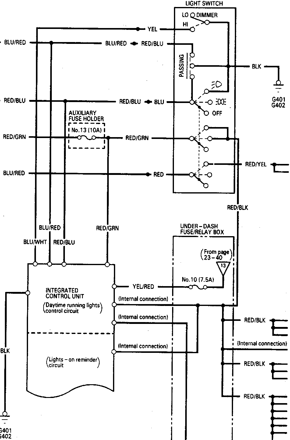
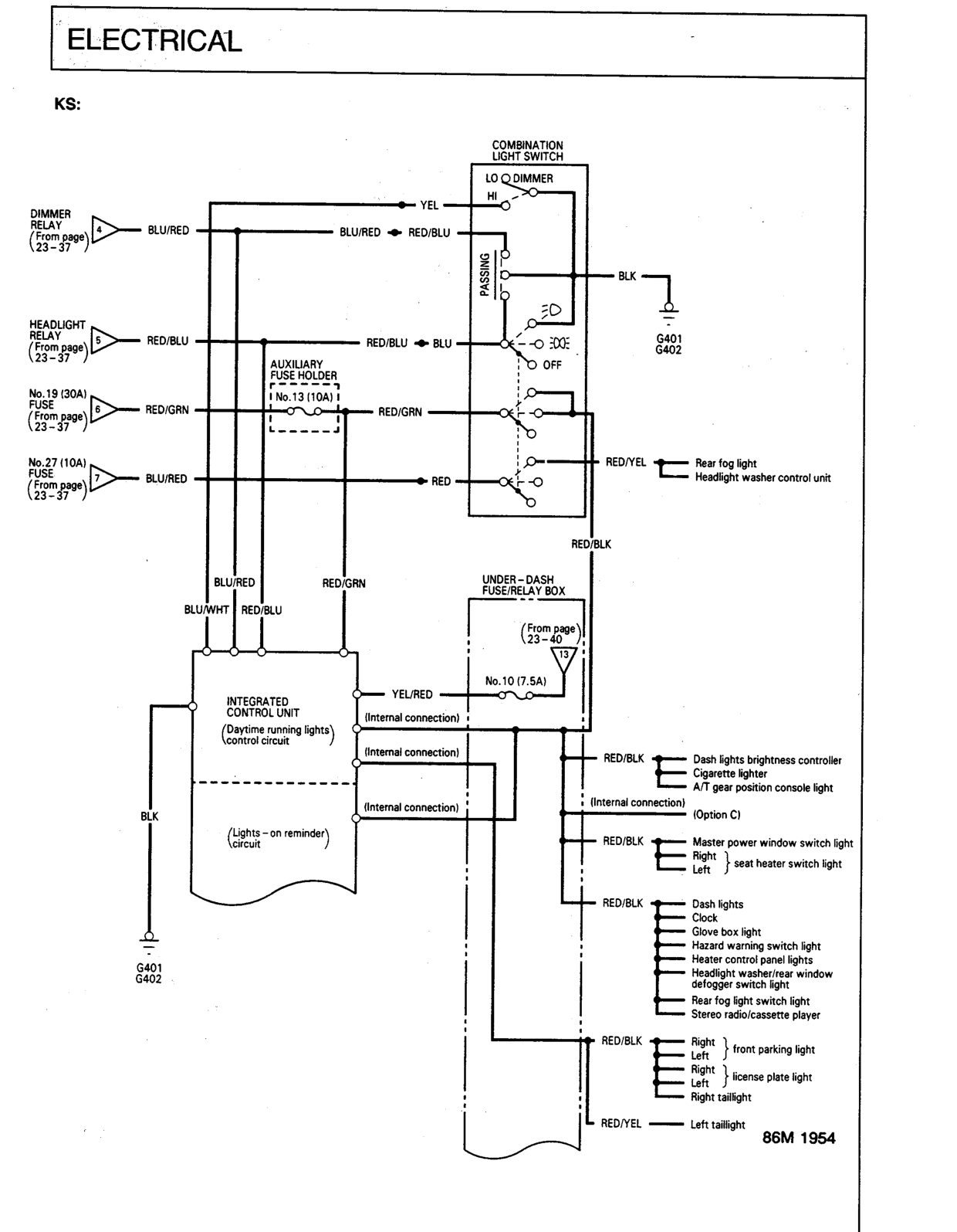
COMBINATION LIGHT SWITCH
- LO DIMMER
- HI
- PASSING
- OFF
AUXILIARY FUSE HOLDER
- No. 13 (10A)
UNDER-DASH FUSE/RELAY BOX
- (From page 23-40)
- No. 10 (7.5A)
INTEGRATED CONTROL UNIT
- (Daytime running lights control circuit)
- (Lights-on reminder circuit)
RED/BLK
- Dash lights brightness controller
- Cigarette lighter
- A/T gear position console light
- (Option C)
- Master power window switch light
- Right { seat heater switch light
- Left { seat heater switch light
RED/BLK
- Dash lights
- Clock
- Glove box light
- Hazard warning switch light
- Heater control panel lights
- Headlight washer/rear window defogger switch light
- Rear fog light switch light
- Stereo radio/cassette player
RED/BLK
- Right { front parking light
- Left { front parking light
- Right { license plate light
- Left { license plate light
- Right taillight
RED/YEL
- Left taillight

Original page
Parts & tools for this job For Rover 600
- TOOLDigital multimeterSearch: automotive digital multimeter
- PARTAssorted fuse kitSearch: car fuse assortment kit
- TOOLWire crimper and connector kitSearch: wire crimper connector kit
Links open Amazon search results in a new tab. As an Amazon Associate I earn from qualifying purchases.