Workshop Manuals Factory service & repair Rover
01 Information02 General data03 Engine04 Engine management system – PGM-Fi05 Cooling system, manifold and exhaust06 Clutch07 Manual gearbox08 Automatic gearbox09 Drive shafts10 Differential – manual gearbox11 Differential – automatic gearbox12 Steering13 Suspension14 Brakes and ABS15 Brakes – ABS BY416 Body17 Heating and ventilation18 Electrical19 Supplementary restraint system (SRS)
Rover Rover 600 Repair Manual - Volumes 1 and 2 - 2nd Edition18 · Electrical
18 · Electrical

86M 1971

Make
Rover
Model
600 Rover 600 Repair Manual - Volumes 1 and 2 - 2nd Edition
Section
Wire harness and earth locations › 86M 1971
Electrical86M 1971 · page 1 of 2
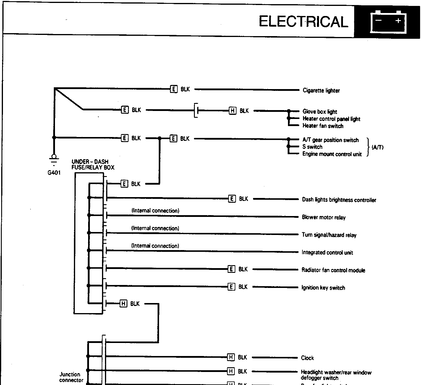
Electrical wiring diagram showing connections from the under-dash fuse/relay box and junction connector to various components including cigarette lighter, glove box light, heater controls, A/T gear position switch, blower motor relay, turn signal/hazard relay, integrated control unit, radiator fan control module, ignition key switch, clock, headlight washer/rear window defogger switch, rear fog light switch, rear fog light switch light, and gauge assembly.
Under-dash fuse/relay box and junction connector connections
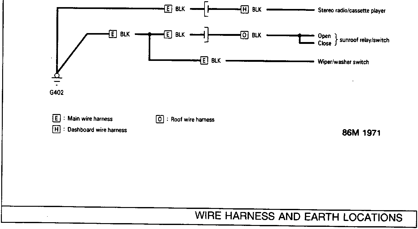
Electrical wiring diagram showing connections from ground point G402 to stereo radio/cassette player, sunroof relay/switch (open/close), and wiper/washer switch.
Stereo, sunroof, and wiper/washer switch connections

E : Main wire harness
H : Dashboard wire harness
O : Roof wire harness

86M 1971

Parts & tools for this job For Rover 600

Links open Amazon search results in a new tab. As an Amazon Associate I earn from qualifying purchases.