
Under – dash fuse/relay box
- Make
- Rover
- Model
- 600 Rover 600 Repair Manual - Volumes 1 and 2 - 2nd Edition
- Section
- Wire harness and earth locations › Under – dash fuse/relay box
ElectricalUnder – dash fuse/relay box
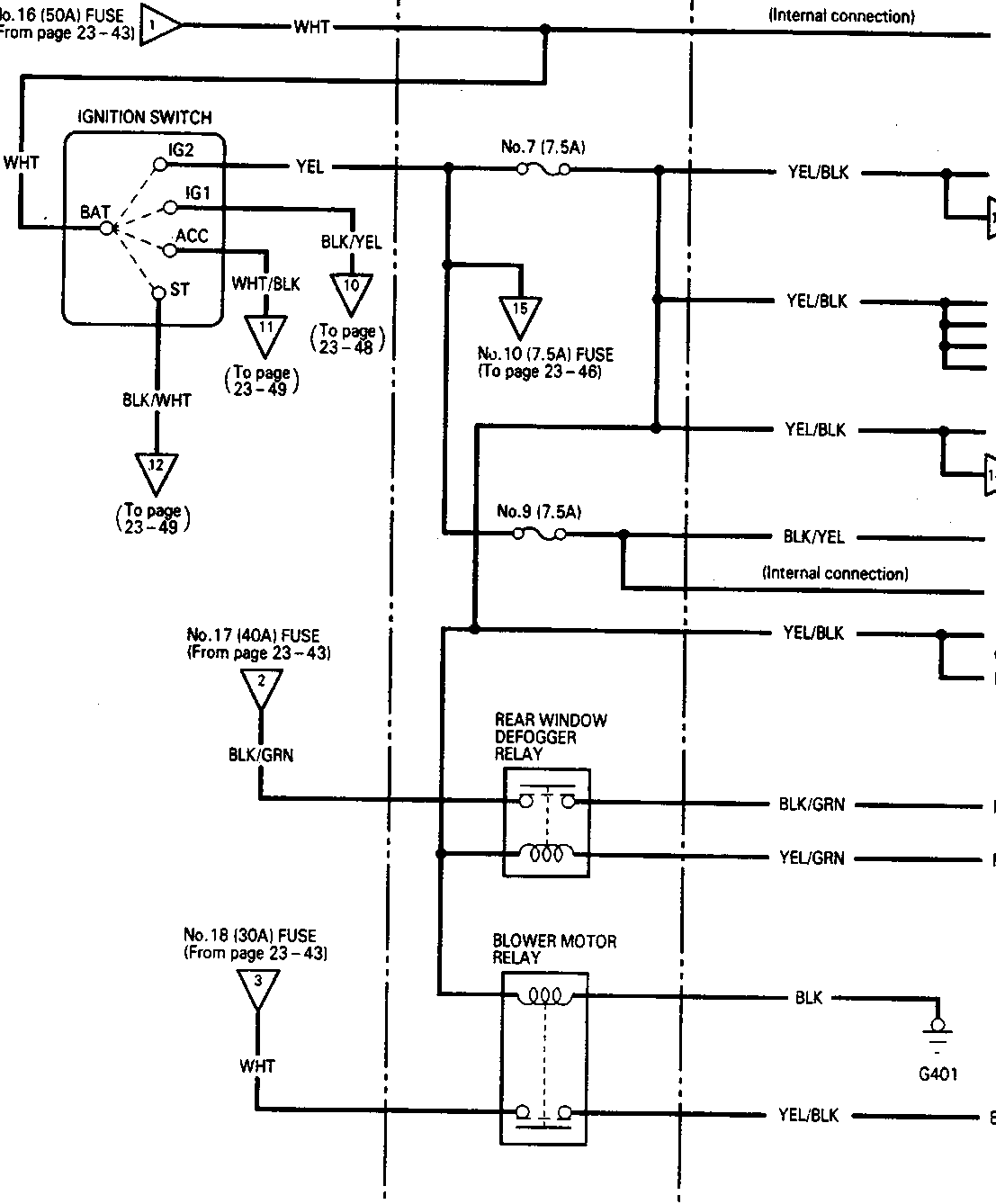
UNDER – DASH FUSE/RELAY BOX
No.19 (50A) FUSE
(from page 23–43)
IGNITION SWITCH
- IG2
- IG1
- ACC
- ST
BAT
WHT
YEL
BLK/YEL
WHT/BLK
BLK/WHT
No.7 (7.5A)
No.10 (7.5A) FUSE
(To page 23–46)
No.9 (7.5A)
No.17 (40A) FUSE
(From page 23–43)
No.18 (30A) FUSE
(From page 23–43)
Radiator fan control module
RADIATOR FAN RELAY
(To page 23–43)
ABS control unit
ABS inspection connector
Front
Rear
ABS fail – safe relay
Recirculation control motor
ABS MOTOR RELAY
(To page 23–43)
A/C compressor clutch relay
Headlight washer/rear window defogger switch
Heater control panel
REAR WINDOW DEFOGGER RELAY
Rear window defogger
Rear window defogger switch
BLOWER MOTOR RELAY
G401
Blower motor
Parts & tools for this job For Rover 600
- TOOLDigital multimeterSearch: automotive digital multimeter
- PARTAssorted fuse kitSearch: car fuse assortment kit
- TOOLWire crimper and connector kitSearch: wire crimper connector kit
Links open Amazon search results in a new tab. As an Amazon Associate I earn from qualifying purchases.