
Gasket - cylinder head (page 9 of 9)
- Make
- Land Rover
- Model
- Discovery II (UK)
- Section
- Overhaul
Engine - Td5Gasket - cylinder head · page 9 of 9
- Compare figures obtained with camshaft bearing clearance: l Camshaft bearing clearance = 0.04 to 0.10 mm (0.002 to 0.004 in)
- If any bearing clearance is found to exceed figures given, repeat the above procedures using a new camshaft. If, after repeating the clearance check using a new camshaft the clearances are still excessive, a new cylinder head and camshaft carrier assembly must be fitted.
- Remove all traces of Plastigage using an oily cloth, do not use a scraper.
- On completion, discard camshaft carrier bolts.
- Check free length of valve springs: l Free length = 46.75 to 47.25 mm (1.84 to 1.86 in)
- Replace valve springs as a set, if springs are to be refitted, keep them in their fitted order.
- Clean carbon from valves, check valves for burning, pitting or cracking; replace as necessary.
- Clean carbon from valve seat inserts, remove all loose particles on completion.
- Check valve seat inserts for pitting and burning. It is not permissible to recut or replace valve seat inserts.
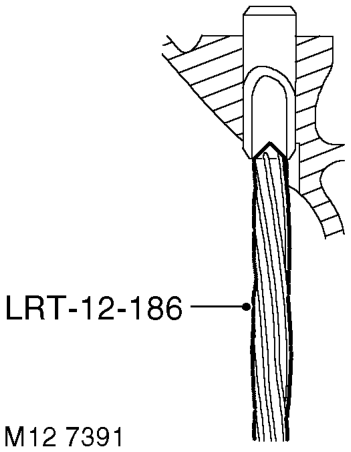
- Remove carbon deposits from valve guides using tool LRT-12-186 inserted from the combustion chamber face side of cylinder head. Ensure all loose particles of carbon are removed on completion.
- Check and record diameter of each valve stem: l Valve stem diameter - Inlet = 6.907 to 6.923 mm (0.2719 to 0.2725 in) l Valve stem diameter - Exhaust = 6.897 to 6.913 mm (0.2715 to 0.2721 in)
- Renew any valve if stem diameter is less than specified.
- Check and record valve stem to guide clearance using the following procedures.
- Insert each valve into its respective guide.
- Extend valve head 10 mm (0.375 in) out of valve seat and position a DTI gauge to rear of valve head.
- Move valve towards front of cylinder head and zero DTI gauge ensuring that stylus of gauge remains in contact with valve head.
- Move valve towards rear of cylinder head, record gauge reading to give valve stem to guide clearance: l Inlet valve = 0.025 to 0.059 mm (0.0009 to 0.0023 in) l Exhaust valve = 0.035 to 0.069 mm (0.0013 to 0.0027 in)
- If stem to guide clearance exceeds figures given and valve stem diameters were as specified, cylinder head assembly must be replaced; it is not possible to replace valve guides.
- Repeat above procedures for remaining valves. Keep valves in their fitted order.
- Check face angle of each valve, renew any valve with incorrect face angles, do not attempt to recut. l Valve face angle - inlet = 29° 48' ± 12' l Valve face angle - exhaust = 44° 48' ± 12'
- Lap each valve to its seat using grinding paste.
- Apply Prussion Blue to valve seat, insert valve into guide and press it firmly, without rotating on to seat.
- Remove valve and check that a continuous, even line of Prussian Blue has been transferred on to valve face. Note that line does not have to be across whole width of valve face.
- Remove all traces of grinding paste on completion.
- Check valve head stand down using the following procedures.
Parts & tools for this job For Land Rover Discovery
- PARTEngine gasket setSearch: Land Rover Discovery engine gasket set
- TOOLTorque wrenchSearch: 3/8 inch torque wrench
- TOOLFeeler gauge setSearch: feeler gauge set
Links open Amazon search results in a new tab. As an Amazon Associate I earn from qualifying purchases.