
Lrt-12-037 (page 2 of 2)
- Make
- Land Rover
- Model
- Discovery II (UK)
- Section
- Overhaul
Engine - V8Lrt-12-037 · page 2 of 2
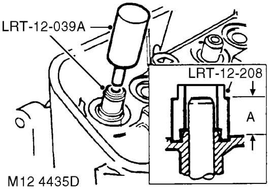
- Lubricate new valve guide with engine oil and with tapered portion of guide leading, insert guide from valve spring side of head. Note: Service valve guides are 0.025 mm (0.001 in) oversize on outside diameter to ensure an interference fit.
- Fully fit guide using tool LRT-12-039A and distance piece tool LRT-12-208 l Valve guide installed height 'A' = 15.00 mm (0.590 in).
- Ream valve guide to 8.70 mm (0.342 in).
- Position cylinder head stands and mount cylinder head on stands.
- Check valve seat insert for pitting, burning, cracks and wear. Replace as necessary. Service valve seat inserts are available 0.025 mm (0.001 in) oversize on outside diameter to ensure interference fit.
- Remove worn valve seat.
CAUTION: Take care not to damage the counterbore in the cylinder head when removing valve seats.
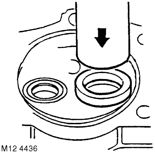
- Heat cylinder head evenly to approximately 120° C (250°F).
WARNING: Handle the hot cylinder head with care.
- Using a suitable mandrel, press new insert fully into counterbore.
- Allow cylinder head to air cool.
CAUTION: Renew worn valve guides and/or valve seats before lapping the valves.
- Recut valve seat in head and lap in valves using fine paste.
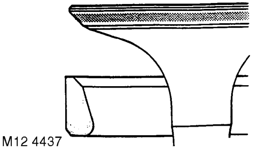
- Coat valve with a small quantity of engineer's blue, insert valve and press into position several times without rotating. Seating position should be in centre of valve face.
Parts & tools for this job For Land Rover Discovery
- PARTEngine gasket setSearch: Land Rover Discovery engine gasket set
- TOOLTorque wrenchSearch: 3/8 inch torque wrench
- TOOLFeeler gauge setSearch: feeler gauge set
Links open Amazon search results in a new tab. As an Amazon Associate I earn from qualifying purchases.