
Brake master cylinder - ’l’ series
- Make
- Rover
- Model
- 400 Workshop Manual
- Year
- 1995–2000
- Section
- Repairs › Brake master cylinder - ’l’ series
BrakesBrake master cylinder - ’l’ series
BRAKE MASTER CYLINDER - ’L’ SERIES
Service repair no - 70.30.08
Remove
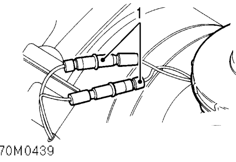
- Disconnect fluid level switch leads.
- Position cloth under master cylinder to absorb fluid spillage.
CAUTION: Do not allow brake fluid to contact paint finished surfaces as paint may be damaged. If spilled, remove fluid and clean area with clean warm water.
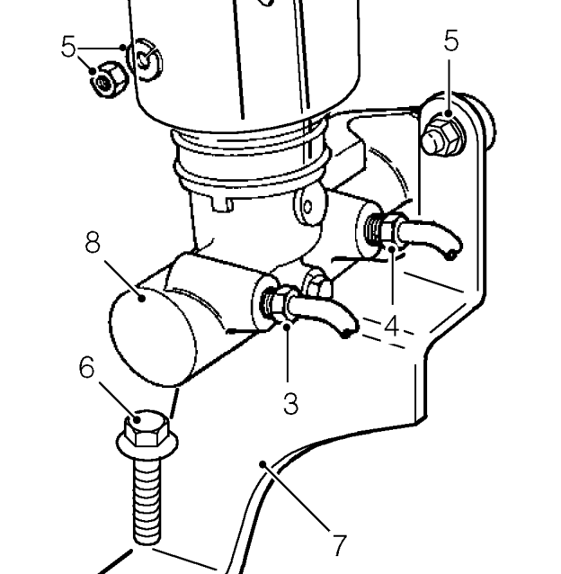
- Disconnect secondary system pipe union from master cylinder.
- Disconnect primary system pipe union from master cylinder.
CAUTION: Plug the connections.
- Remove 2 nuts and spring washers securing master cylinder and support bracket.
- Remove bolt securing support bracket to valance.
- Remove support bracket.
- Remove master cylinder.
Refit
- Clean master cylinder and servo mating surfaces.
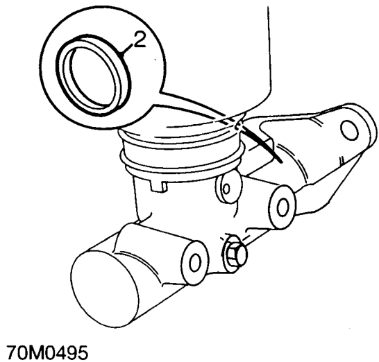
- Ensure rod seal is fitted to master cylinder.
- Align servo push rod and fit master cylinder to servo.
- Fit support bracket to servo studs and fit bolt to valance.
- Fit nuts and spring washers, tighten to 15 Nm.
- Connect primary and secondary brake pipes, tighten unions to 19 Nm.
- Connect fluid level switch leads.
- Bleed brakes. See Adjustments.
Parts & tools for this job For 1995 Rover 400
- TOOLBrake bleeder kitSearch: one man brake bleeder kit
- FLUIDBrake fluidSearch: brake fluid
- TOOLBrake line flaring toolSearch: brake line flaring tool
Links open Amazon search results in a new tab. As an Amazon Associate I earn from qualifying purchases.