
Front brake disc
- Make
- Rover
- Model
- 400 Workshop Manual
- Year
- 1995–2000
- Section
- Repairs › Front brake disc
BrakesFront brake disc
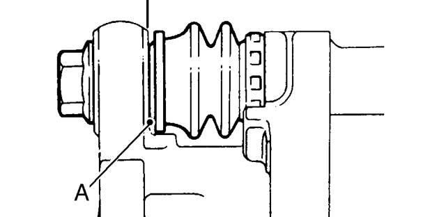
- Position caliper housing to carrier, align flats ’A’ on guide pins with lugs on caliper housing. Fit guide pin bolts and tighten to 27 Nm.
- Clean banjo bolt and fit NEW sealing washers.
- Position hose to caliper and tighten banjo bolt to 34 Nm.
- Remove clamp from brake hose.
- Bleed brakes. See Adjustments.
- Fit road wheel(s) and tighten nuts to correct torque. See INFORMATION, Torque wrench settings.
- Remove stand(s) and lower vehicle.
FRONT BRAKE DISC
Service repair no - 70.10.10
Remove
CAUTION: Brake discs must be renewed in pairs unless one disc requires changing before 1000 miles (1500 km) from new.
- Raise front of vehicle.
WARNING: Support on safety stands.
- Remove road wheel(s).
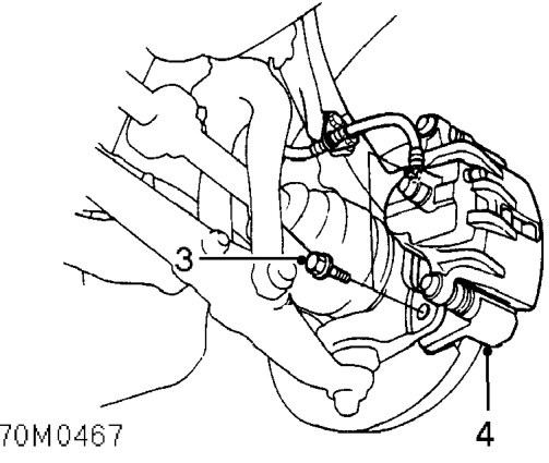
- Remove 2 bolts securing brake caliper to swivel hub.
- Release caliper and tie aside clear of brake disc.
CAUTION: Do not allow caliper to hang on brake hose.
Parts & tools for this job For 1995 Rover 400
- PARTFront brake padsSearch: Rover 400 1995 front brake pads
- TOOLCaliper piston rewind toolSearch: brake caliper piston rewind tool
- FLUIDBrake fluidSearch: brake fluid
Links open Amazon search results in a new tab. As an Amazon Associate I earn from qualifying purchases.