
Crankshaft pulley (page 2 of 3)
- Make
- Rover
- Model
- 400 Workshop Manual
- Year
- 1995–2000
- Section
- Repairs
Engine - L SeriesCrankshaft pulley · page 2 of 3
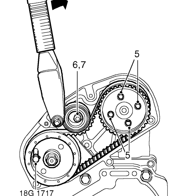
- Insert locking pin 18G 1717 through injection pump drive gear and into hole in adapter plate. Locking pin must be a sliding fit. If pin is a tight fit, proceed as follows:
- Loosen 4 bolts securing camshaft gear to hub.
- Loosen timing belt tensioner Allen bolt.
- Using a torque wrench fitted to tensioner pulley backplate, apply a clockwise, as viewed from rear of engine, torque loading of 6 Nm to drive belt. Maintain loading and tighten tensioner pulley Allen bolt to 44 Nm.
CAUTION: Do not exceed specified torque figure.
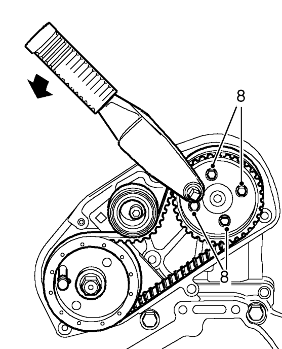
- Fit torque wrench to FIP drive belt gear as shown and apply an anti-clockwise, as viewed from rear of engine, torque loading of 25 Nm. Maintain loading and tighten 4 bolts securing gear to 25 Nm.
- Remove FIP gear locking pin 18G 1717 and timing pin 18G 1523.
Parts & tools for this job For 1995 Rover 400
- PARTEngine gasket setSearch: Rover 400 1995 engine gasket set
- TOOLTorque wrenchSearch: 3/8 inch torque wrench
- TOOLFeeler gauge setSearch: feeler gauge set
Links open Amazon search results in a new tab. As an Amazon Associate I earn from qualifying purchases.