
Models with air conditioning (page 2 of 3)
- Make
- Rover
- Model
- 400 Workshop Manual
- Year
- 1995–2000
- Section
- Repairs
Engine - L SeriesModels with air conditioning · page 2 of 3
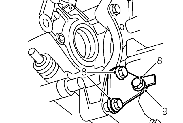
- Remove 3 bolts securing support bracket to gearbox and sump.
- Remove bracket.
- Position container to collect spillage from vacuum pump and oil cooler pipe unions.
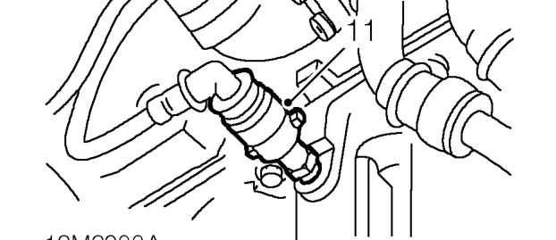
- Release vacuum pump oil return pipe from adaptor on sump.
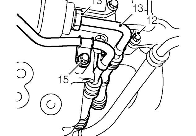
- Remove bolt securing oil cooler pipe clip to bracket on coolant pump mounting.
- Remove oil cooler pipe union nut from oil pump and release pipe from pump.
- Remove and discard ’O’ ring.
CAUTION: Plug the connections.
- Remove 2 bolts securing oil cooler pipe to sump.
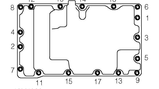
- Using sequence shown, remove 17 bolts securing sump to cylinder block.
- Remove sump.
- Remove and discard gasket from sump.
Parts & tools for this job For 1995 Rover 400
- TOOLA/C manifold gauge setSearch: AC manifold gauge set
- TOOLUV leak detection kitSearch: AC UV leak detection kit
- PARTCabin filterSearch: Rover 400 1995 cabin filter
Links open Amazon search results in a new tab. As an Amazon Associate I earn from qualifying purchases.