
Engine control module - ’t’ series
- Make
- Rover
- Model
- 400 Workshop Manual
- Year
- 1995–2000
- Section
- Repairs › Engine control module - ’t’ series
Engine management system - MEMSEngine control module - ’t’ series
Refit
- Position ignition coil to mounting bracket.
- Fit bolts and nuts securing ignition coil to mounting bracket and tighten to 9 Nm.
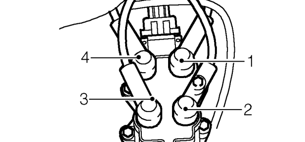
- Connect h.t. leads to ignition coil in order shown.
- Connect multiplug to ignition coil.
- Align evaporative emissions charcoal canister to mounting bracket and secure.
- Connect battery earth lead.
ENGINE CONTROL MODULE - ’T’ SERIES
Service repair no - 18.30.01
Remove
- Disconnect battery earth lead.
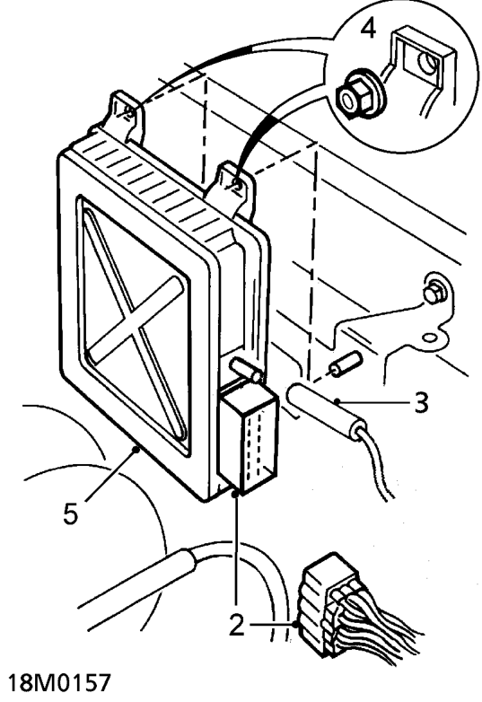
- Disconnect multiplug from engine control module.
- Disconnect vacuum hose from engine control module.
- Remove 2 nuts securing engine control module to mounting bracket.
- Release engine control module from lower fixing grommet and remove module.
Parts & tools for this job For 1995 Rover 400
- TOOLOBD2 scannerSearch: OBD2 scanner
- TOOLDigital multimeterSearch: automotive digital multimeter
- TOOLBack-probe test leadsSearch: back probe test leads
Links open Amazon search results in a new tab. As an Amazon Associate I earn from qualifying purchases.