
Heated oxygen sensor - ’t’ series
- Make
- Rover
- Model
- 400 Workshop Manual
- Year
- 1995–2000
- Section
- Repairs › Heated oxygen sensor - ’t’ series
Engine management system - MEMSHeated oxygen sensor - ’t’ series · page 1 of 2
HEATED OXYGEN SENSOR - ’T’ SERIES
Service repair no - 19.22.16
Remove
- Disconnect battery earth lead.
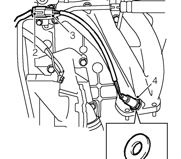
- Disconnect sensor multiplug.
- Release multiplug from bracket.
- Using a 22 mm crow foot spanner, remove sensor and collect sealing washer.
Refit
- Fit NEW sealing washer to sensor.
- Fit sensor to manifold and tighten to 55 Nm.
- Connect sensor multiplug and secure to bracket.
- Connect battery earth lead.
THROTTLE HOUSING - ’T’ SERIES
Service repair no - 19.22.45
Remove
- Disconnect battery earth lead.
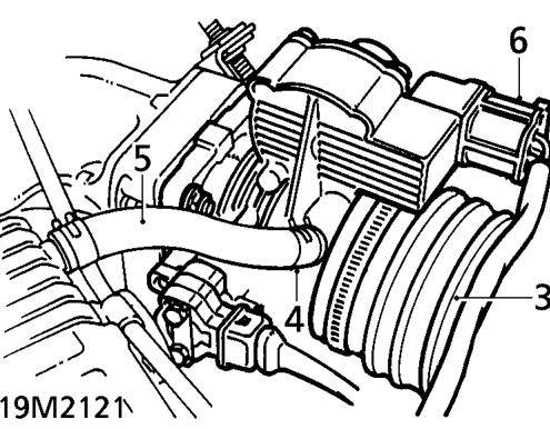
- Loosen clip screw securing air intake hose to throttle housing.
- Release air intake hose from throttle housing.
- Release clip securing breather hose to throttle housing.
- Release breather hose from throttle housing.
- Disconnect multiplugs from stepper motor and throttle position sensor.
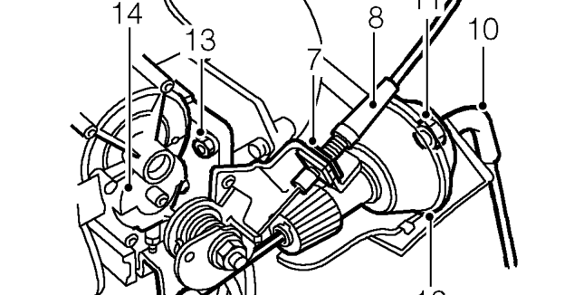
- Release throttle cable adjustment nut from abutment bracket.
- Release throttle cable from cam and position cable aside.
- Release cruise control actuator unit pull rod from throttle lever.
- Release vacuum hose from cruise control actuator unit.
- Remove nut securing cruise control actuator unit to mounting bracket.
- Remove cruise control actuator unit.
Parts & tools for this job For 1995 Rover 400
- PARTOxygen sensorSearch: Rover 400 1995 oxygen sensor
- TOOLOxygen sensor socketSearch: oxygen sensor socket
- TOOLOBD2 scannerSearch: OBD2 scanner
Links open Amazon search results in a new tab. As an Amazon Associate I earn from qualifying purchases.