
Throttle position sensor - ’k’ series
- Make
- Rover
- Model
- 400 Workshop Manual
- Year
- 1995–2000
- Section
- Repairs › Throttle position sensor - ’k’ series
Engine management system - MEMSThrottle position sensor - ’k’ series
THROTTLE POSITION SENSOR - ’K’ SERIES
Service repair no - 18.30.17
Remove
- Disconnect battery earth lead.
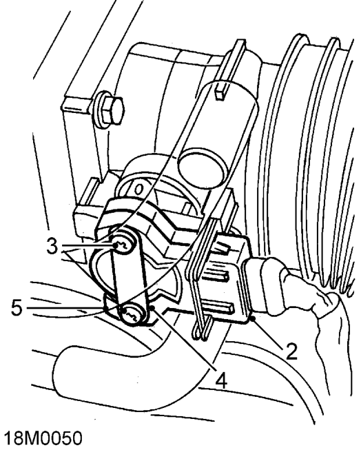
- Disconnect multiplug from throttle position sensor.
- Remove and discard 2 Tx20 Torx screws and wave washers securing throttle position sensor to inlet manifold.
- Remove throttle position sensor specification plate.
- Pull throttle position sensor from throttle spindle.
CAUTION: Do not twist or apply leverage to throttle position sensor.
Refit
- Clean mating faces of throttle housing and throttle position sensor.
- Fit throttle position sensor to throttle spindle. Ensure that during fitting the machined flat on the throttle spindle is aligned with the mating portion of the throttle position sensor.
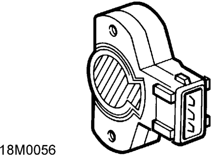
CAUTION: The throttle position sensor can easily be damaged during fitting. When pressing the sensor onto throttle spindle, use fingers only and apply pressure only to the area shown shaded in the illustration.
- Rotate throttle position sensor in a clockwise direction to align fixing holes.
CAUTION: Do not rotate sensor in a clockwise direction and ensure that it is not rotated beyond its internal stops.
- Fit throttle position sensor specification plate.
- Fit new Torx screws and wave washers, tighten Torx screws to 1.5 Nm.
CAUTION: Do not exceed specified torque figure.
- Connect multiplug to throttle position sensor.
- Operate throttle cable cam 2 or 3 times and ensure that full travel to the throttle open and the throttle closed positions is available.
- Connect battery earth lead.
Parts & tools for this job For 1995 Rover 400
- TOOLOBD2 scannerSearch: OBD2 scanner
- TOOLDigital multimeterSearch: automotive digital multimeter
- TOOLBack-probe test leadsSearch: back probe test leads
Links open Amazon search results in a new tab. As an Amazon Associate I earn from qualifying purchases.