
RHD models only
- Make
- Rover
- Model
- 400 Workshop Manual
- Year
- 1995–2000
- Section
- Repairs › RHD models only
Engine management system - MEMSRHD models only
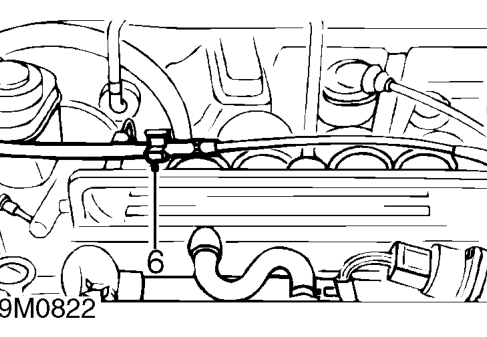
- Release cable from clips on inlet manifold, fuel return pipe and coolant hose.
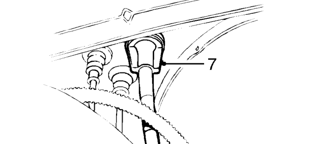
- Release cable from bulkhead.
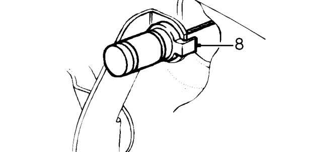
- Depress nylon clips and disconnect throttle cable from pedal and remove cable.
Refit
- Feed new cable through bulkhead and connect inner cable to pedal.
- Smear rubber grease on both sides of the rubber seal and secure cable to bulkhead.
- Refit throttle cable to clips on the fuel return pipe and inlet manifold.
- Connect throttle cable to throttle cam.
RHD models only
- Locate expansion tank on body.
- Fit 2 bolts securing expansion tank to body and tighten to 9 Nm.
- Secure coolant hose to clip on body.
- Secure throttle cable to clip on coolant hose.
All models
- Adjust throttle cable. See Adjustments.
Parts & tools for this job For 1995 Rover 400
- PARTEngine gasket setSearch: Rover 400 1995 engine gasket set
- TOOLTorque wrenchSearch: 3/8 inch torque wrench
- TOOLFeeler gauge setSearch: feeler gauge set
Links open Amazon search results in a new tab. As an Amazon Associate I earn from qualifying purchases.