
Throttle housing - ’k’ series
- Make
- Rover
- Model
- 400 Workshop Manual
- Year
- 1995–2000
- Section
- Repairs › Throttle housing - ’k’ series
Engine management system - MEMSThrottle housing - ’k’ series
THROTTLE HOUSING - ’K’ SERIES
Service repair no - 19.22.45
Remove
- Disconnect battery earth lead.
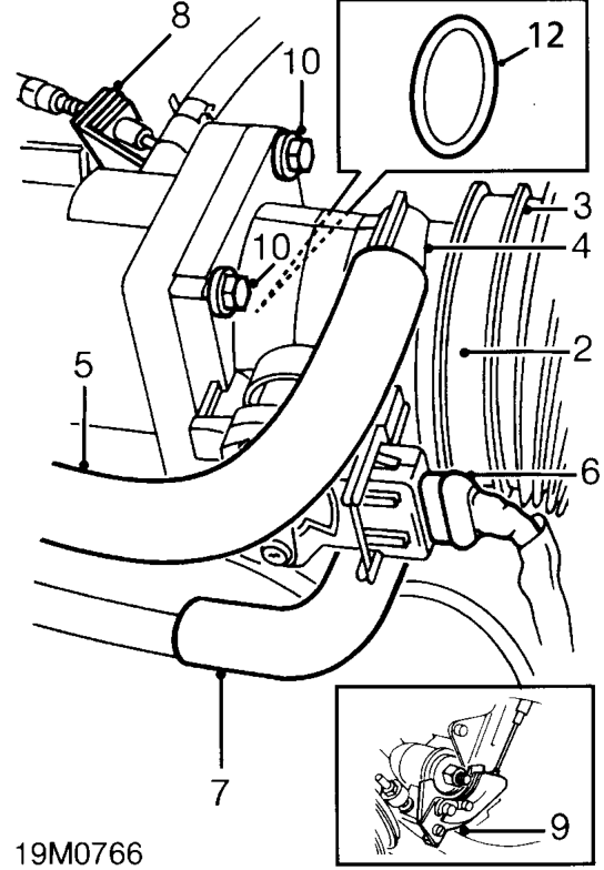
- Release clip and disconnect air intake hose from throttle housing.
- Disconnect hose from throttle housing.
- Disconnect hose from idle air control valve.
- Remove idle air control valve hose.
- Disconnect multiplug from throttle position sensor.
- Release clip and disconnect breather hose from throttle housing.
- Release throttle cable adjusting nut from abutment bracket.
- Disconnect throttle cable from throttle cam.
- Remove 4 bolts securing throttle housing to inlet manifold.
- Remove throttle housing.
- Remove and discard ’O’ ring seal from throttle housing.
Refit
- Clean mating faces of throttle housing and inlet manifold.
- Lubricate new ’O’ ring seal with silicone grease and fit to throttle housing.
- Position throttle housing to inlet manifold, fit bolts and tighten to 7 Nm.
- Connect throttle cable to throttle cam.
- Locate throttle cable adjusting nut in abutment bracket.
- Connect breather hose to inlet manifold and secure with clip.
- Connect multiplug to throttle position sensor.
- Fit idle air control valve hose and align orientation marks.
- Connect hose to throttle housing.
- Connect air intake hose to throttle housing and secure with clip.
- Connect battery earth lead.
Parts & tools for this job For 1995 Rover 400
- PARTEngine gasket setSearch: Rover 400 1995 engine gasket set
- TOOLTorque wrenchSearch: 3/8 inch torque wrench
- TOOLFeeler gauge setSearch: feeler gauge set
Links open Amazon search results in a new tab. As an Amazon Associate I earn from qualifying purchases.