
Front lower ball joint (page 4 of 4)
- Make
- Rover
- Model
- 400 Workshop Manual
- Year
- 1995–2000
- Section
- Repairs
SuspensionFront lower ball joint · page 4 of 4
Refit
CAUTION: There are two types of lower ball joint available. Ensure the correct ball joint is fitted to the vehicle:
’K’ & ’D’ series - Small diameter RBK 100380 ’L’ & ’T’ series - Larger diameter RBK 100350 (identified by 5mm unthreaded end)
- Remove spring clip securing boot on new ball joint and remove boot.
CAUTION: Do not allow dirt to enter boot or ball joint.
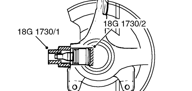
- Position ball joint to swivel hub and fit tools 18G 1730/1 and 18G1730/2 . Position assembly in vice and use vice to press ball joint into swivel hub.
- Remove swivel hub and tools from vice.

- Fit circlip.
- Clean grease off ball pin taper and boot installation section and fit boot.
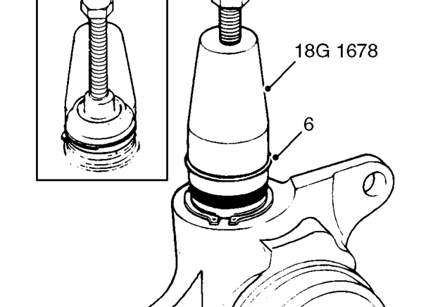
- Fit tool 18G 1678 over boot and adjust bolt to align end of tool with spring clip groove in boot. Slide spring clip over tool to secure boot.
- Clean disc shield and swivel hub mating faces.
- Align disc shield, fit screws and tighten to 5 Nm.
- Fit hub ring.
- Position swivel hub assembly to drive shaft and engage lower ball joint to lower arm. Fit nut and tighten to 49 Nm, align nut to next split pin hole and fit new split pin.
- Connect upper ball joint, fit nut and tighten to 39 Nm, align nut to next split pin hole and fit new split pin.
- Connect steering arm ball joint, fit nut and tighten to 39 Nm, align nut to next split pin hole and fit new split pin.
- Fit ABS sensor to adaptor, fit Torx screw and tighten to 9 Nm.
- Position sensor lead brackets to swivel hub, fit bolts and tighten to 10 Nm.
- Clean disc and drive flange mating faces.
- Fit disc to drive flange, align reference marks, fit screws and tighten to 10 Nm.
- Position caliper, fit bolts and tighten to 108 Nm.
- Align brake hose bracket, fit bolts and tighten to 10 Nm.
- Fit new drive shaft nut and tighten to 181 Nm. Stake nut to shaft.
- Fit road wheel(s) and tighten nuts to correct torque. See INFORMATION, Torque wrench settings.
- Remove stand(s) and lower vehicle.
Parts & tools for this job For 1995 Rover 400
- TOOLTie rod end toolSearch: tie rod end puller
- TOOLBall joint separatorSearch: ball joint separator
- FLUIDPower steering fluidSearch: Rover power steering fluid
Links open Amazon search results in a new tab. As an Amazon Associate I earn from qualifying purchases.