
Original page
- Make
- Rover
- Model
- 600 Rover 600 Repair Manual - Volumes 1 and 2 - 2nd Edition
- Section
- Interior fittings › Original page
BodyOriginal page
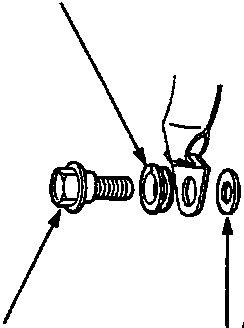
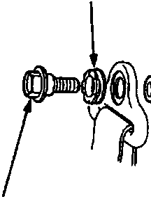
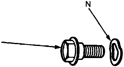
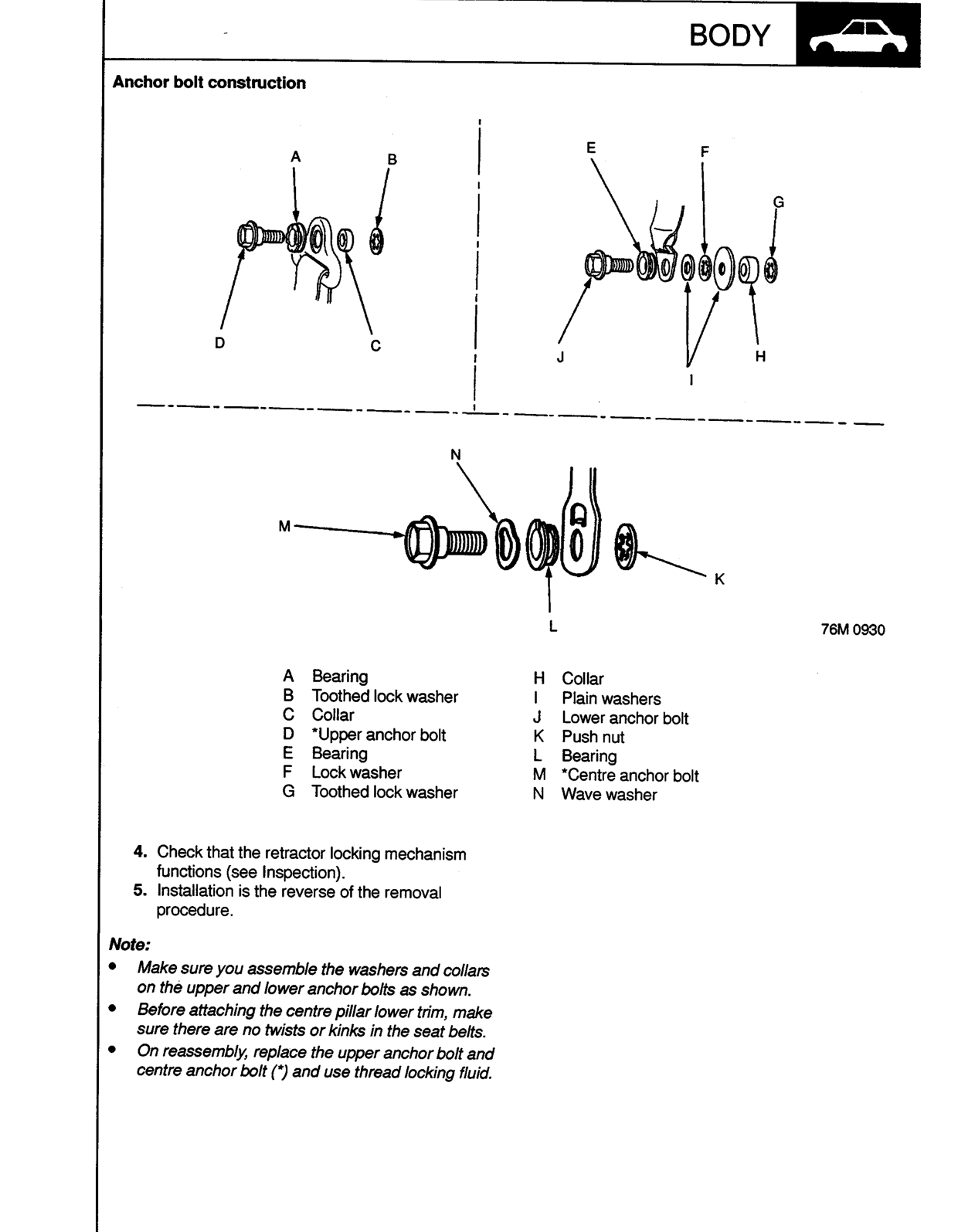
76M 0930
| A | Bearing | H | Collar |
| B | Toothed lock washer | I | Plain washers |
| C | Collar | J | Lower anchor bolt |
| D | *Upper anchor bolt | K | Push nut |
| E | Bearing | L | Bearing |
| F | Lock washer | M | *Centre anchor bolt |
| G | Toothed lock washer | N | Wave washer |
- Check that the retractor locking mechanism functions (see Inspection).
- Installation is the reverse of the removal procedure.
Note:
- Make sure you assemble the washers and collars on the upper and lower anchor bolts as shown.
- Before attaching the centre pillar lower trim, make sure there are no twists or kinks in the seat belts.
- On reassembly, replace the upper anchor bolt and centre anchor bolt (*) and use thread locking fluid.
Original page
Parts & tools for this job For Rover 600
- TOOLTrim removal tool kitSearch: trim removal tool kit
- PARTTouch-up paintSearch: Rover touch up paint
- PARTPanel clip assortmentSearch: Rover panel clips assortment
Links open Amazon search results in a new tab. As an Amazon Associate I earn from qualifying purchases.