
Replacement
- Make
- Rover
- Model
- 600 Rover 600 Repair Manual - Volumes 1 and 2 - 2nd Edition
- Section
- Interior fittings › Replacement
BodyReplacement
Replacement
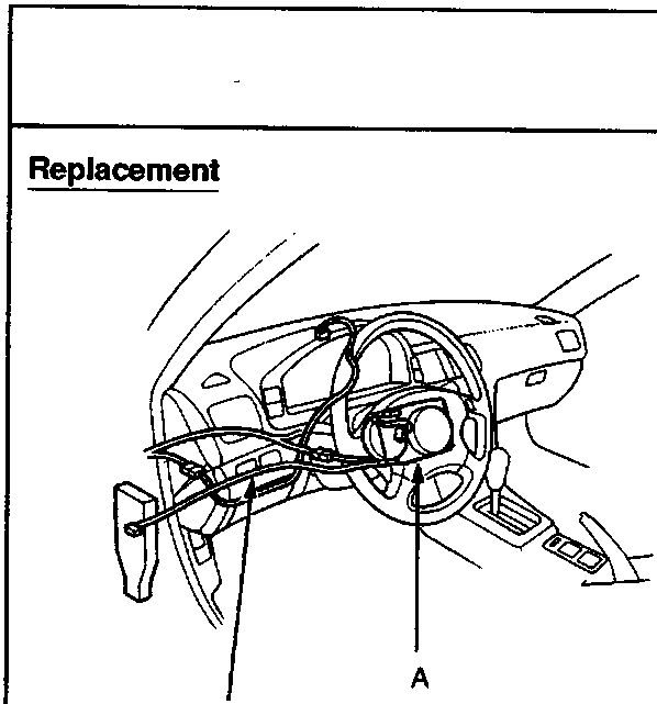
A Airbag assembly
B SRS main harness
SRS wire harnesses are routed near the dashboard and steering column.
CAUTION:
- All SRS electrical wiring harnesses are covered with yellow outer insulation.
- Replace the entire affected SRS harness assembly if it has an open circuit or damaged wiring.
- Before disconnecting the SRS wiring harnesses, turn the ignition switch off, disconnect the negative and positive battery cables, and wait at least three minutes.
- To remove the dashboard, first remove the:
- Front seats
- Front console
- Dashboard lower cover
- Glove box
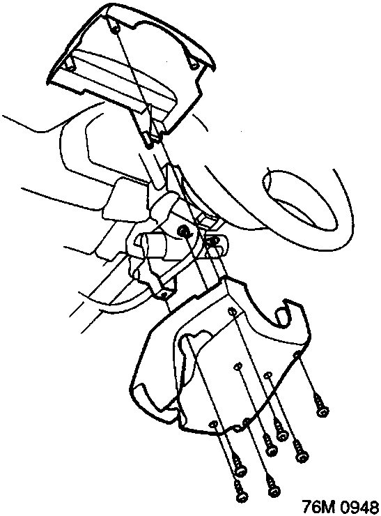
- Remove the steering column covers.
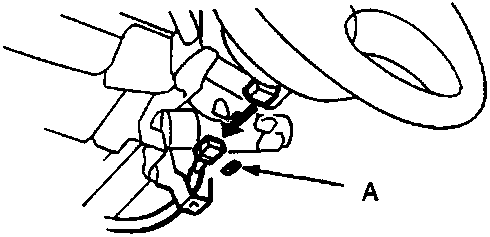
A Connector lock
- Pull out the connector lock, then disconnect the SRS main harness connector from the slip ring.
Parts & tools for this job For Rover 600
- TOOLTrim removal tool kitSearch: trim removal tool kit
- PARTTouch-up paintSearch: Rover touch up paint
- PARTPanel clip assortmentSearch: Rover panel clips assortment
Links open Amazon search results in a new tab. As an Amazon Associate I earn from qualifying purchases.